Jitter
Jitter measurement function is selected by pressing the FUNCTION
JITTER button. It is only available in digital analyzer mode.
The Jitter measurement function measures the jitter (time variation) in
the transitions of a digital signal. It also measures the peak-to-peak
voltage of the digital signal and the frequency of the jitter.
The upper left section of the display shows the jitter measured on the
signal. The upper left soft key selects among the available units, which
are seconds (s) and unit intervals (UI).
The upper center section of the display shows the peak-to-peak voltage
of the incoming digital signal, in Vpp. There are no other units
available. The upper center soft key selects the termination impedance
of the digital input, either HiZ or LoZ. The HiZ option provides a
termination ≥2.5 kΩ on the AES/EBU XLR input and
>3kΩ on the SPDIF/EIAJ BNC input. The LoZ option provides a
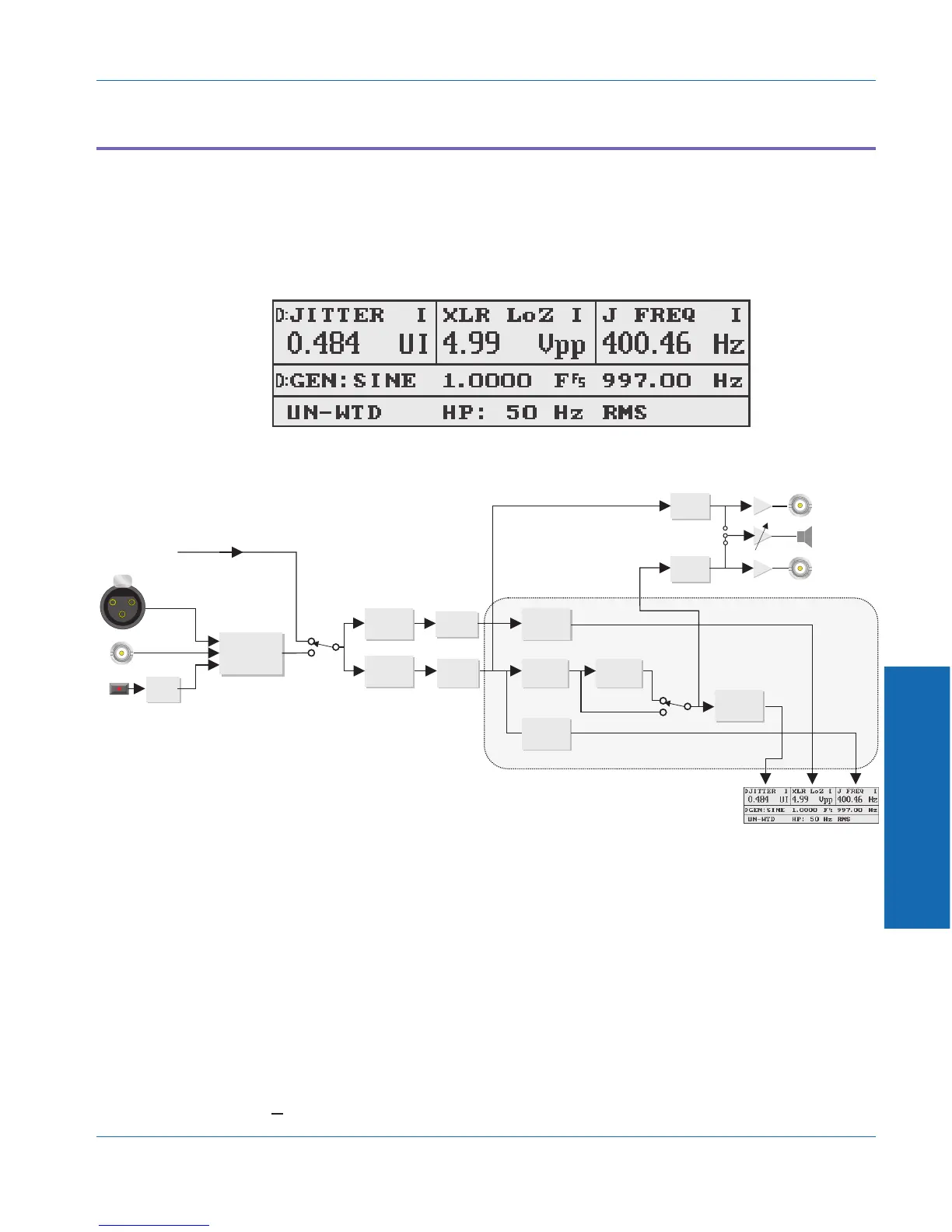
Figure 4-36. Main panel in JITTER function
OPTICAL
RECEIVER
AUTOMATIC
SELECTION
GENERATOR
MONITOR
AC PEAK
DETECTOR
JITTER
DEMODULATOR
A-to-D
CONVERTOR
A-to-D
CONVERTOR
TUNABLE
BANDPASS
FILTER
50 Hz/700 Hz
HIGHPASS
FILTER
FREQUENCY
COUNTER
RMS/PEAK
DETECTOR
READING
DETECTOR
INTERNAL
JUMPER
INPUT
MONITOR
SPEAKER/
HEADPHONE
READING
MONITOR
D-to-A
CONVERTER
D-to-A
CONVERTER
DIGITAL
SIGNAL
PROCESSOR
DIGITAL
INPUTS
Figure 4-37. Blaock diagram of Jitter measurement
4 Functions
Function Descriptions Jitter
ATS-1 Dual Domain User's Manual 4-39