and a ground which is shared by the two. Since it is a two-channel
unbalanced connection, it requires connection to two XLR connectors.
The generator should be set to an unbalanced configuration by
selecting 50 Ω Unbal on ghe Generator panel.
See Figure 3-20. The first configuration shown is preferred because it
offers the highest immunity to interference and noise. However, it may
be difficult to construct because of practical connector limitations. The
other two configurations are also valid for testing applications, but are
considerably more susceptible to interference and grounding problems.
BNC Connector Panel
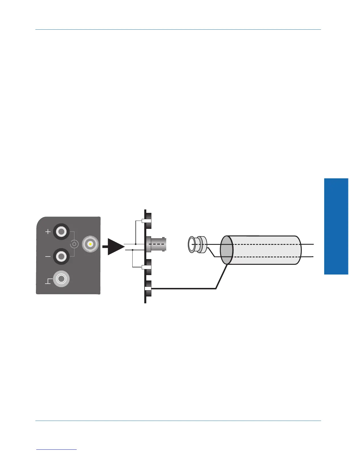
The generator can be configured to deliver a balanced or unbalanced
output to the connector panel. The BNC connector panel, the standard
configuration on the ATS-1 Access and optional for the ATS-1 Dual
Domain, has floating BNC connectors. The preferred configuration is a
balanced output with a two-conductor shielded cable as shown in
Figure 3-21.
2 Conductor shielded cable
Shield not connected this end
BNC Connector
+
--
-
GND
GND
Typical BNC Panel (partial)
+
Figure 3-21. Preferred cable connections with BNC connector panel
3 Operation
Operational Overview External Connections
ATS-1 Dual Domain User's Manual 3-49