Generator Output and Analyzer Input connectors
The analyzer’s analog inputs and the generators analog outputs are
normally mounted on a subpanel mounted on the front of the
instrument, and are shown that way in the figures in this manual.
However, this subpanel can be interchanged with the speaker panel
on the rear if preferred. Refer to Appendix C for procedure.
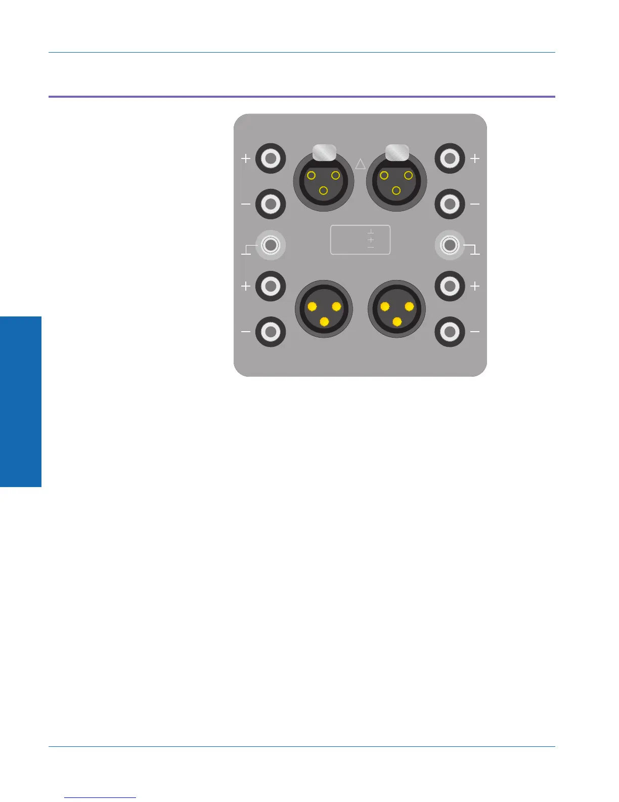
The connectors on this subpanel are normally three-pin XLR
connectors and banana jacks. Panels with alternative connector styles
may be substituted when the instrument is ordered, or changed later
in the field. The alternative styles include:
.
BNC and banana jack connectors;
.
WE-310 tip-ring-sleeve and banana jack connectors;
.
1/4-inch phone and banana jack connectors.
!
350Vpk MAX
CAT II
PIN 1 =
PIN 2 =
PIN 3 =
AB
AB
GENERATOR OUTPUTS
ANALYZER INPUTS
Figure 3-14. Standard XLR Connector Panel
3 Operation
Generator Output and Analyzer Input connectors Operational Overview
3-34 ATS-1 Dual Domain User's Manual