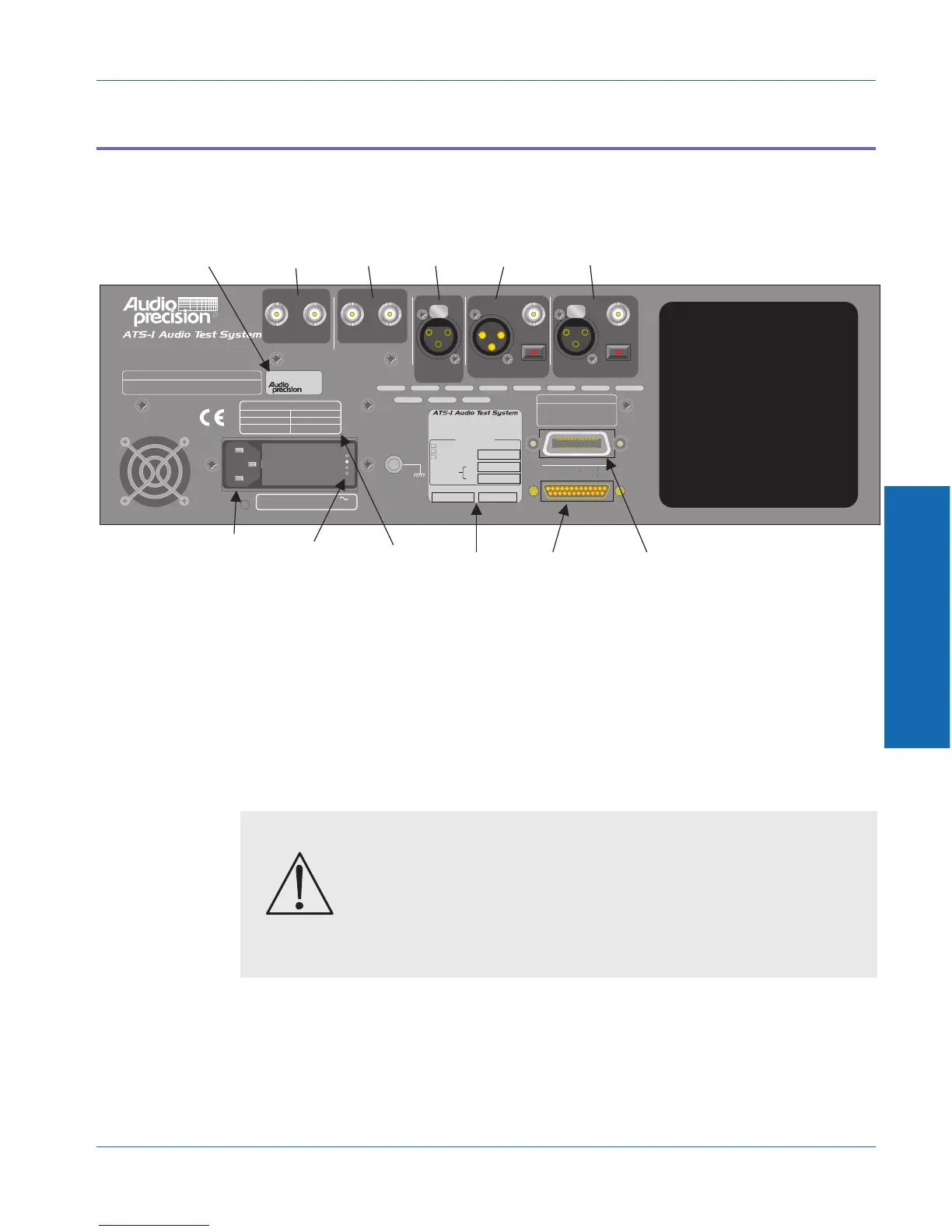
Rear Panel Connectors
Figure shows an overview of the rear panel. The following sections
describe each connector.
Digital Inputs and Outputs
The ATS-1 Dual Domain’s rear panel includes connectors for XLR,
BNC, and optical input and output connections. Digital devices
typically use XLR connectors (using the AES/EBU standard) for
balanced connections and BNC (using the SPDIF standard) for
unbalanced connections. An optical link can also be used.
The appropriate ATS-1 Dual Domain digital output should be
connected to the digital input of the device under test. The appropriate
ATS-1 Dual Domain digital input should be connected to the digital
output of the device under test.
ANALYZER
5Vpp MAX
OPTICAL
BALBAL
DIGITAL OUTPUT
INPUT
REFERENCE
TRIGGER SIGNALS
INPUT ANALOG DIGITAL
UNBAL UNBAL
5Vpp MAX
OPTICAL
MONITORS
DIGITAL INPUT
IEEE-488 INTERFACE
RL1, PP0, DC1, DT1, C0, E1
SH1, AH1, T6, TE0, L4, LE0, SR1,
250mA T/SB 250V
500mA T/SB 250V
FREQUENCY: 50/60 Hz MAXIMUM POWER: 60 VA
SUPPLY VOLTAGE: 100/120/230/240 VAC
FUSE REPLACEMENT DATA
230/240 VAC
100/120 VAC
SUPPLY VOLTAGE FUSE
INSTRUMENT RESET
To restore factory default instrument settings,
hold dBr button and turn on mains power switch.
4,614,914; 4,563,652; 4,631,522; 5,089,981; 5,136,267; 5,265,201;
5,247,458; 5,420,516; 5,336,989.
Other patent applications pending.
This product is protected under one or more of the following patents:
Manufactured in Beaverton, Oregon, USA
GPIB ADDRESS
To set instrument GPIB address,
use utility menu under PANELS
selection on front panel.
R
ATS1-XXXXX
Date of manufacture Code
Audio Measurement System
DUAL DOMAIN
Aux 2:
Aux 1:
Opt'l Filters:
Installed Options:
Special
EGZ Euro. Impedances
P1P-488 GPIB Inter.
P1-IMD Intermod. Distortion
UNBAL
OPTICAL
100 V
120 V
230 V
240 V
OPTIONS
LABEL
GPIB
CONNECTOR
(SPEAKER PANEL)
PRINTER
CONNECTOR
SERIAL NUMBER
LABEL
MONITOR
OUTPUTS
TRIGGER
OUTPUTS
DIGITAL
REFERENCE
INPUT
DIGITAL
GENERATOR
OUTPUTS
DIGITAL
ANALYZER
INPUTS
FUSE
REPLACEMENT
DATA
POWER
CORD
CONNECTOR
LINE
VOLTAGE
INDICATOR
HOLES
Figure 3-15. Rear panel overview
CAUTION - To avoid serious misoperation of the device
under test, do not use the XLR output connector for an
unbalanced connection. If your device requires
unbalanced input, always use the BNC output connector.
3 Operation
Operational Overview Generator Output and Analyzer Input connectors
ATS-1 Dual Domain User's Manual 3-35