In the digital domain only:
.
Jitter
.
Digital data integrity
.
Sample rate, amplitude, and delay of digital carrier signal
.
Status Bits
Analog and Digital Modes
The Analyzer has two distinct modes: analog and digital. For most
measurement functions, the selection of analog or digital mode only
determines whether the input to the measurement is analog or digital.
A few measurement functions are only available in one domain or the
other.
The analog/digital mode switching is controlled by the analog/digital
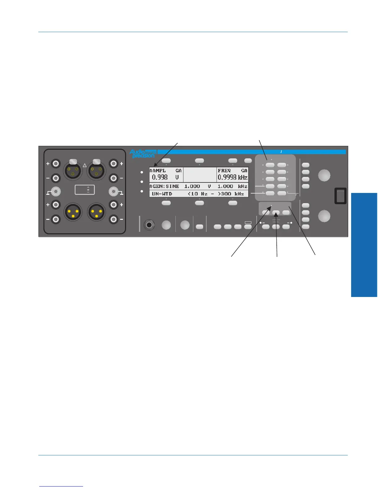
button. The mode can be determined by the analog/digital indicator.
The word ‘DIGITAL’ or ‘ANALOG’ will be lit, depending on the mode.
It can also be determined by the letter in the top left corner of the
display. If the analyzer is currently in analog mode, ‘A:’ will appear. If
the analyzer is currently in digital mode, ‘D:’ will appear.
Note that the analyzer’s analog/digital mode is separate from the
generator’s analog/digital mode. They may both be in analog mode
DIGITAL
FREQUENCY
MONITOR
CONTRAST
RECALL
SAVE
PRINT
PANELS BARGRAPH SWEEP
INSTRUMENT MODE
dBr ZERO
POWER
ADDR
REM
SRQ
ATS- Dual Domain Audio Test System
INPUT
OUTPUT
AB
GEN LOAD
DATA
-10
INC
10
x
.
.
DEC
AMPLITUDE
DEC
+10dB
INC
-10dB
AB
AC MAINS
DIGITAL I/O
JITTER
W+F
XTALK
RATIOIMD
PHASE
SINAD
THD+N/
LEVEL
AMPL/
NOISE
FUNCTION
ANALOG
FUNCTION
KEYS
This unit is currently in
analog analyzer mode
INPUT
CONTROL
KEYS
ANALOG/DIGITAL
BUTTON
ANALOG/DIGITAL
MODE INDICATOR
!
350Vpk MAX
CAT II
PIN 1 =
PIN 2 =
PIN 3 =
AB
AB
GENERATOR OUTPUTS
ANALYZER INTPUTS
Figure 3-13. Analyzer Control Keys
3 Operation
Operational Overview Controlling the Analyzer
ATS-1 Dual Domain User's Manual 3-23