Analog Analyzer Input Circuit
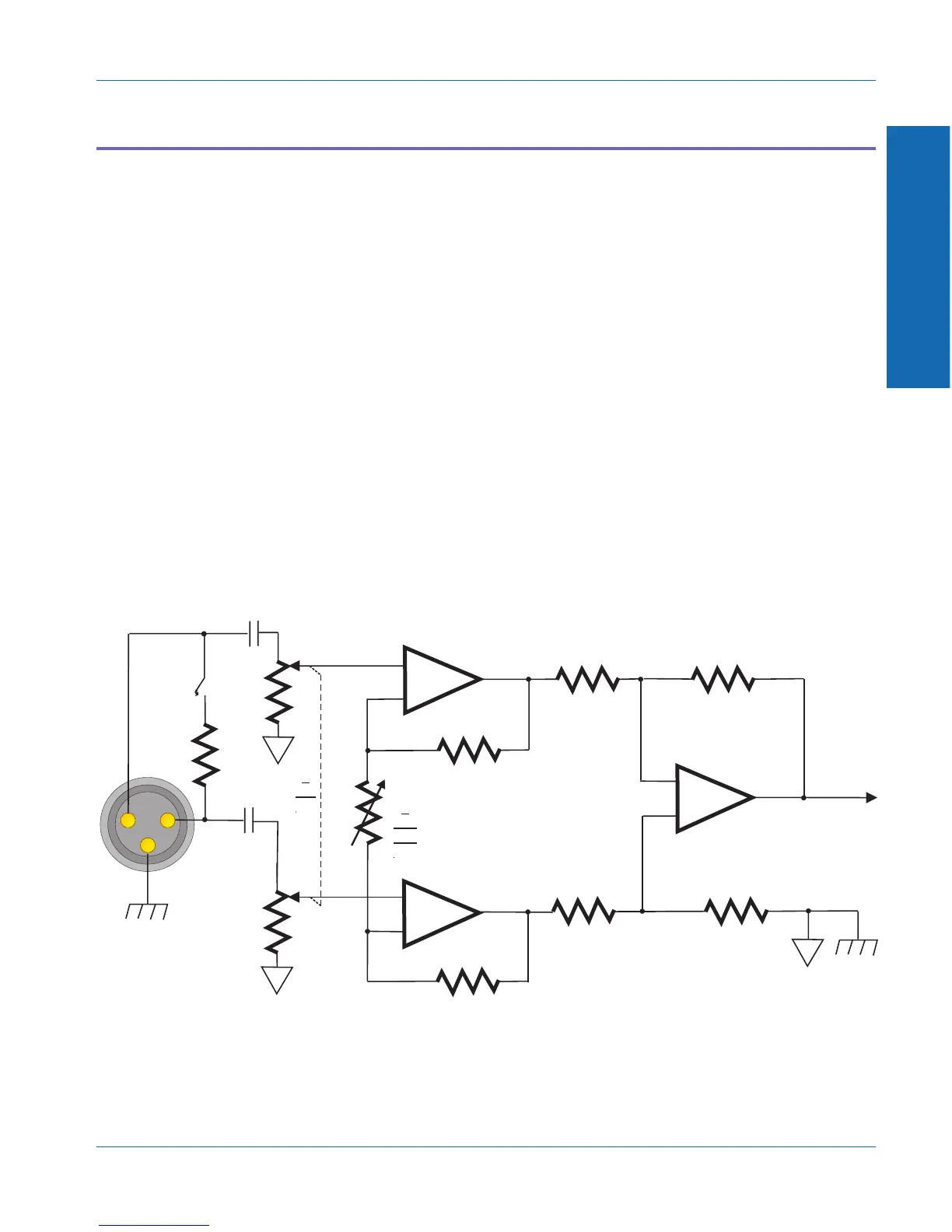
Figure 1-9 is a simplified diagram of one channel of the analog
analyzer input.
The circuit is a true instrument-grade differential (balanced) input.
Both sides (pins 2 and 3) are loaded with 100 kΩ to ground, high
enough to bridge most audio circuits. The net gain from the input
connector to the analyzer proper is set by a combination of
compensated resistive attenuators (zero, 20 dB, or 40 dB attenuation)
and switchable-gain amplifiers (zero, +10 dB, +20 dB or +30 dB
gain). Both the attenuator setting and the amplifier gain are
microprocessor-controlled as part of the automatic ranging circuit, to
maintain the signal level fed to the remainder of the analyzer at an
optimum level for low noise and distortion.
If the 600 Ω input termination is selected (as shown in Figure 1-9), the
application of an input voltage greater than 30 V rms will cause the
termination to disconnect to prevent damaging the termination.
3
2
1
+
--
+
--
+
--
1Fµ1Fµ
1Fµ1Fµ
600 Ω600 Ω
Input Attenuator
0
+10
+20
+30
0
+10
+20
+30
0
-20
-40
0
-20
-40
To Analyzer
Figure 1-9. Simplified analog analyzer input circuit
1 Description
Description Analog Analyzer Input Circuit
ATS-1 Dual Domain User's Manual 1-17