The following diagrams show examples of the flags display.
The incoming Confidence and Validity flags are also shown as part of
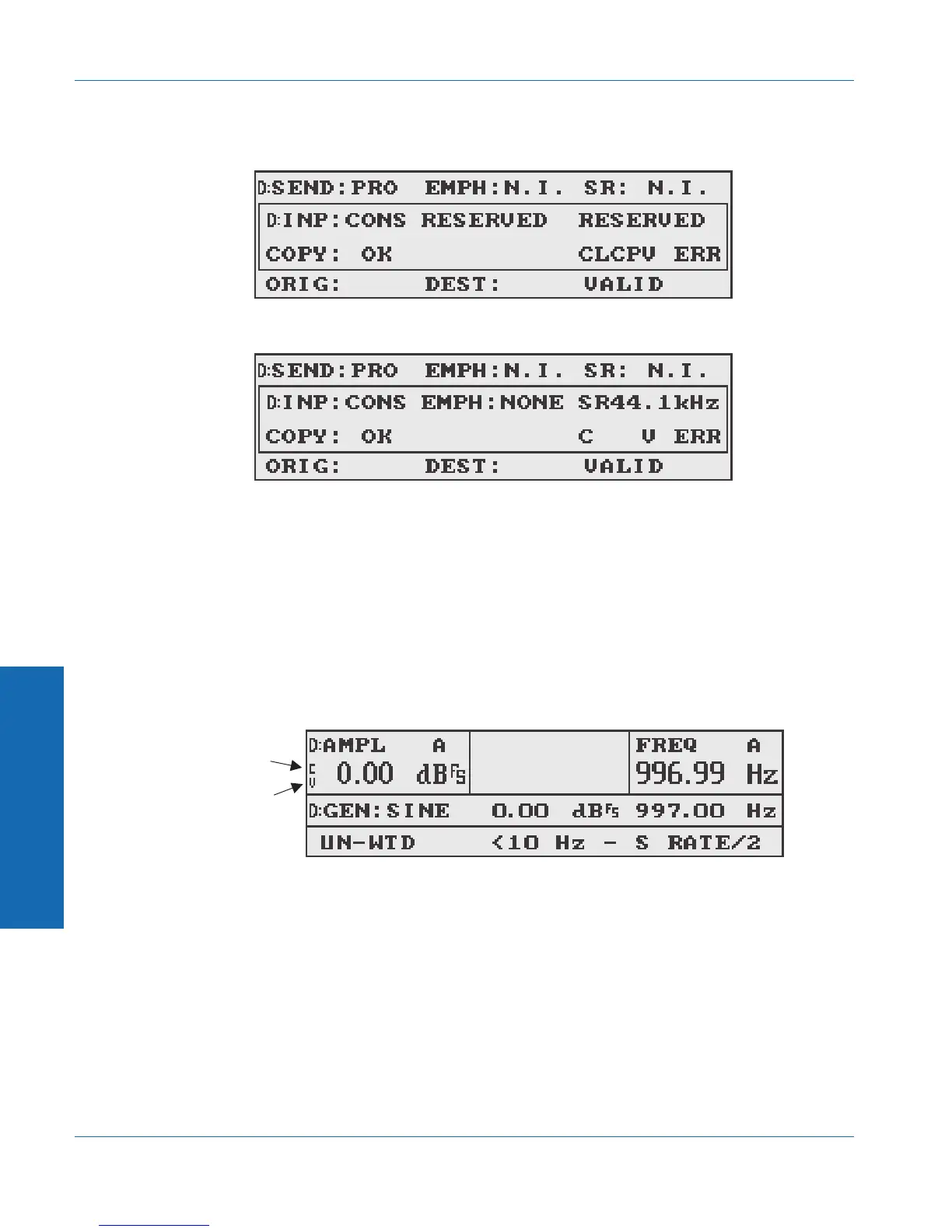
the main reading in any of the digital measurement functions. If the
Confidence flag is active (indicating poor confidence), a small ‘C’ is
shown to the left of the main measurement. If the Validity flag is
active (indicating invalid data), a small ‘V’ is shown to the left of the
main measurement. Following is an example of the Confidence and
Validity flags in digital AMPL mode:
A small ‘J’ may also appear in this area of the display, indicating that
the jitter generator is on. The J appears in the same place as the
Validity flag, but the Validity flag takes priority. If the Validity flag
indicates invalid data and the jitter generator is on, only the V will be
shown.
Figure 4-44. All Error flags active
Figure 4-45. Confidence and Validity flags active
CONFIDENCE
FLAG
VALIDITY
FLAG
Figure 4-46. Confidence and Validity flags in reading display
& For more
information on
generating jtiter,
see page 3-18.
4 Functions
Status Bits Function Descriptions
4-50 ATS-1 Dual Domain User's Manual