1. Remove the top cover (only) as described earlier in this section.
2. Locate the digital assembly, which is enclosed in a metal case near
the rear of the unit. The cable to be changed is located on the
right front corner of the digital assembly, as shown on Figure
C-3.
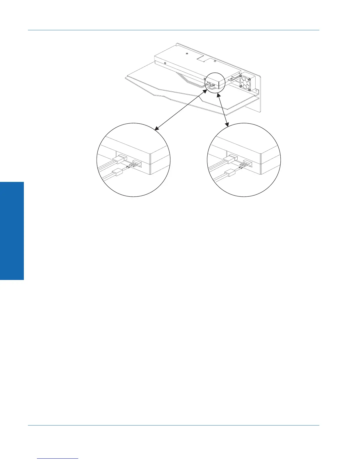
3. The cable connector has three pins that stick out from the metal
case. The cable connects to either the left two pins or the right
two pins (see Figure C-3). With the cable in Position A, the
monitor signal will come from the input. With the cable in
Position B, the monitor signal will come from the final processed
reading. The polarity of the connection does not matter. Move
the cable to the desired position.
4. Replace the top cover.
Position A Position B
Figure C-3. Cable positions for monitor selection
C Internal Changes
Appendix C - Performing Internal Changes Monitor Source Selection
C-8 ATS-1 Dual Domain User's Manual