USER’S MANUAL / bit Tune /
10
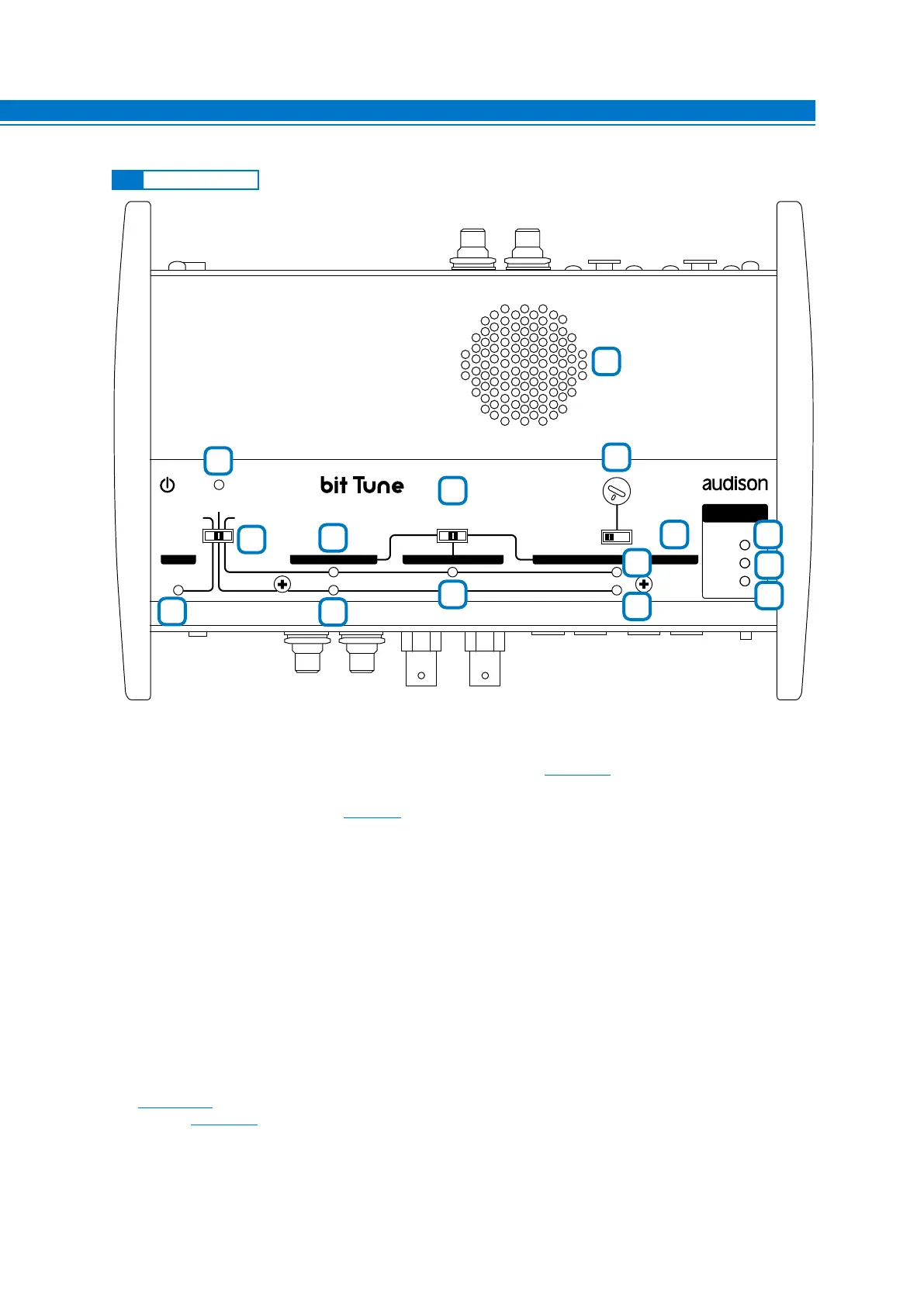
1. POWER: The blue LED indicates that the bit Tune is powered on.
2. EMS - LINE NOISE - PC ANALYZER: Switch for selecting measurement settings.
3. PROBE: The yellow LED indicates that the EMS socket is activated
(see sect. 8.4).
4. PRE IN PC ANALYZER LED: Green LED, indicates the PRE IN input selection for measurements performed
through the bit Tune PC software
(see sect. 7).
5. PRE IN LINE NOISE LED: Yellow LED, indicates the PRE IN input selection for the measurement of noise
through the internal speaker monitor of the bit Tune.
6. SIGNAL INPUT SELECT:
Switch for the selection of PRE IN, BNC, SPK IN measurement inputs of the bit Tune.
7. BNC PC ANALYZER LED: Green LED, indicates the PRE IN input selection for measurements performed
through the bit Tune PC software.
8. SPK IN PC ANALYZER LED: Green LED, indicates the SPK IN input selection for measurements performed
through the bit Tune PC software.
9. SPK IN LINE NOISE LED: Yellow LED, indicates the SPK IN input selection for measurements performed
through the bit Tune PC software
10. VOLUME: Volume control of the internal speaker monitor of the bit Tune.
11. Ch LEFT Ch RIGHT: Switch for selecting the SPK IN Left or Right input in line noise analyzer mode.
12-13-14. LOAD SIMULATOR SPEAKER IN: Through the SPEAKER IN LOAD SIMULATOR-SELECTOR button
(see sect. 3.2.6) it is possible to verify, through the switching of the LEDs, if the source requires a load for operating
properly
(see sect. 8.1).
NO LOAD: Green LED. No load.
47 OHM: Yellow LED. Requires a 47 Ohm - 5 W resistance.
SPK IN: Orange LED. Requires an inductive load.
15. SPEAKER MONITOR: Internal speaker for monitoring audio signal inputs to the bit Tune.
3.3 CONTROL PANEL
EMS
PC ANALYZER
LINE NOISE
POWER
SIGNAL INPUT
SELECT
RIGHT
VOLUME
MONITOR
47 OHM
SPK SYM
NO LOAD
LEFT
PRE IN BNC SPK INPROBE
MIN • • MAX
LOAD SIMULATOR
SPEAKER IN
1
2
4
5
6
3
7
8
9
10
15
1211
13
14
3