USER’S MANUAL / bit Tune /
8
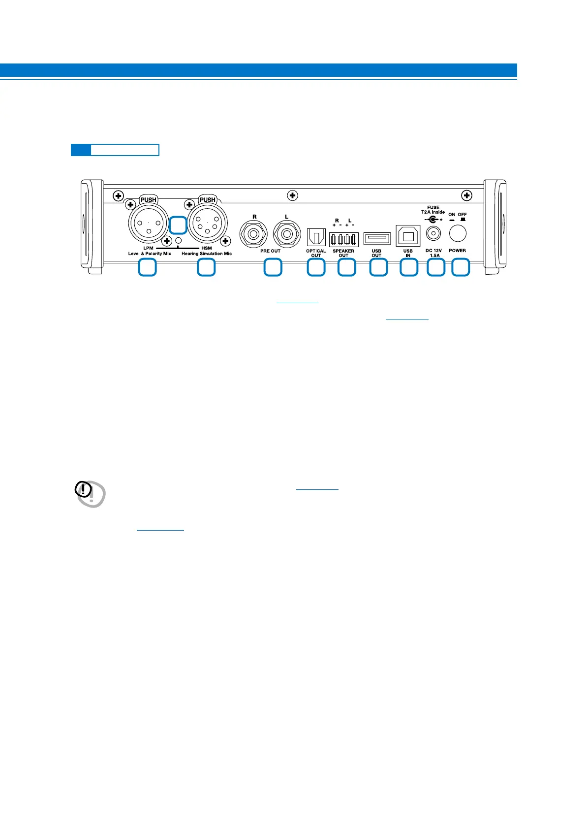
3. DESCRIPTION OF CONNECTION PANELS
1. LPM Level Polarity Mic: LPM Microphone input. (see sect. 3.5).
2. HSM Hearing Simulation Mic: Microphone input for HSM multi-microphone.
(see sect. 3.4).
3. Check MIC: Indicator of microphone sockets activation during measurement.
4. PRE OUT L-R: Low-level analog signal output.
5. OPTICAL OUT: S/PDIF digital optical output STEREO 192 kHz/24bit MAX.
6. SPEAKER OUT R + - L + -: High-level outputs that can be activated to test the ART function of amplifiers,
processors.
7. USB OUT: USB (A) connection socket, to connect an Audison processor (bit One, bit Ten, bit Ten D) to the bit
Tune and manage the calibration functions. The connection standard is USB 1.1 / 2.0 compatible.
8. USB IN: USB (B) connection socket, to connect the processor to a PC and manage functions via the bit Tune
PC software. The connection standard is USB 1.1 / 2.0 compatible.
9. DC 12V: Jack for external power supply. Please use the power adapters supplied with the product.
10. POWER ON/OFF: Button for turning the product on and off. The blue POWER LED indicates that the product is
switched on
(see sect. 4.1.3).
3.1 FRONT PANEL
WARNING: Observe the polarity and supply voltage (12 V DC) provided on the product’s screen print label. An
incorrect connection may damage the bit Tune
(see sect. 9.4).
1 2 4 5 6 7 8 9
10
3
3