USER’S MANUAL / bit Tune /
59
EMS
PC ANALYZER
LINE NOISE
POWER
SEGNAL INPUT
SELECT
RIGHT
VOLUME
MONITOR
47 OHM
SPK SYM
NO LOAD
LEFT
PRE IN BNCSPK INPROBE
MIN •• MAX
LOAD SIMULATOR
SPEAKER IN
PHONE
REM
IN
REM
OUT
12V
KEY
SW
INPUTS
MUTE IN FL FR RRRL
AD Link
AC Link
LEVEL LEVEL
DISCONNECT
THE SPEAKER
SIGNAL
INPUTS
AUX
INPUTS
PRE
INPUTS
DON’T CONNECT PRE IN
CABLE INPUTS WHEN USING
SPK IN INPUTS
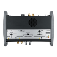
Fig. 2
1. Connect the bit Tune to the Audison bit processor, as shown in fig. 1 or 2 (see points A and B).
- Disconnect all speaker wires from the system’s speakers.
- Set the sensitivity level of the amplifiers to the minimum (5 V RMS).
- Turn the bit Tune on and connect the USB cable to the PC.
- Set the function switch of the bit Tune to PC ANALYZER.
- Set the SIGNAL INPUT SELECT switch on SPEAKER IN.
- Turn on the Audison bit processor and connect the USB cable to the bit Tune.
- Start the bit Tune software by clicking the icon on the PC desktop created by the installation and launch the
software in bit Tune + Processor mode.
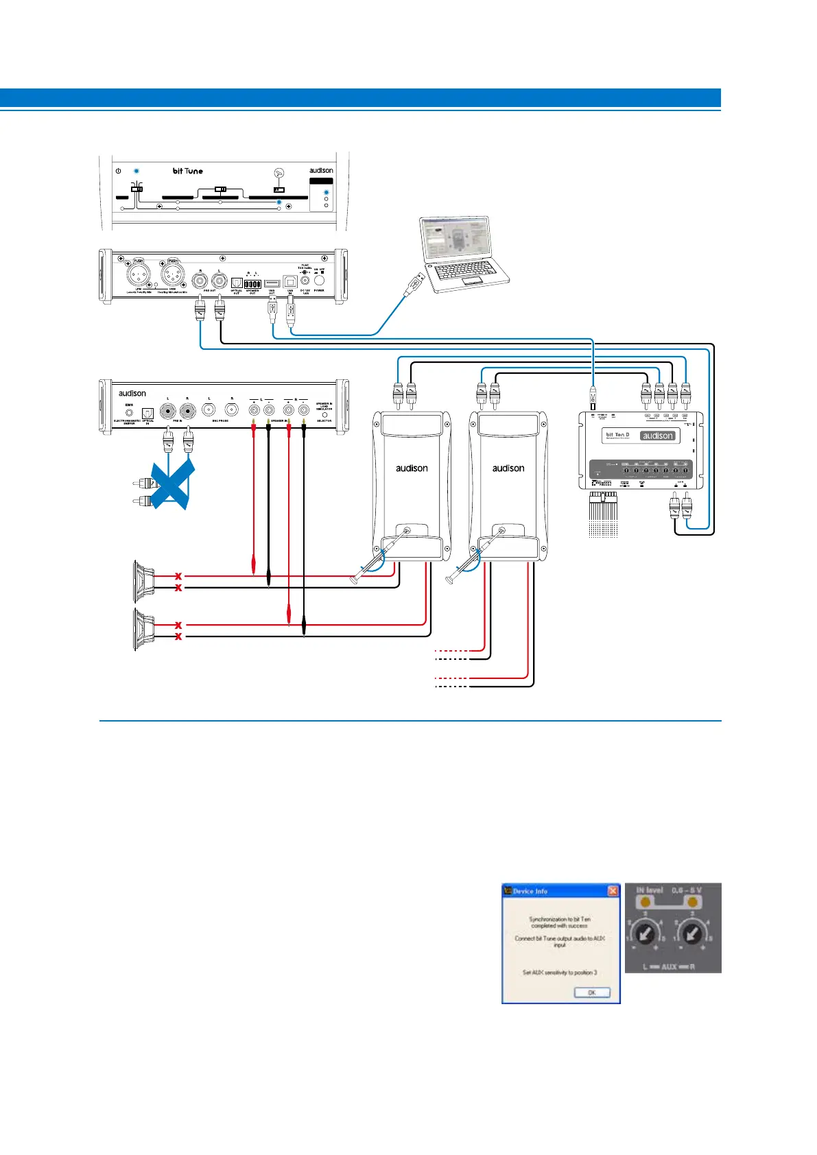
A. bit Ten: Connect the AUX Left and Right inputs of the bit Ten
to the Pre Out Left and Right outputs of the bit Tune, and set
the level of the AUX inputs to position 1.
B. bit One: Connect the AUX1 Left and Right inputs of the
bit Ten to the Pre Out Left and Right outputs of the bit Tune.
7