- 6P10 PILOT MANUAL
-
11
It is mandatory to refer to the technical manual provided with each water tank.
It is
mandatory to install a safety group on the cold water inlet of each water tank.
Do not place a stop valve between the safety group and the water tank.
• The number of elbows and pressure losses will have to be minimize, focets will have to be adapted.
• Areas in which domestic water is rich in limestone (HT > 15), we advise the installation of an anti-scale device on the domestic water inlet. The
hydrotimetric title has to be less than 15.
• The concentration in chlorides in DHW has to be less than 60mg/L (required quality for drinkable water intented for human consumption).
Domestic Hot Water can reach more than 60°C, (especially during the anti-legionelosis protection), it is
mandatory to install a thermostatic valve on the DHW outlet to avoid any risk of burn.
4.2.1.10 - Installation of the DHW circuit
4.2.1.11 - Purging the installation
The oxygen present in the air is extremely corrosive. All necessary measures must be taken to ensure that the installation can be continuously
purged. Automatic air purging valves should be placed at each high point of the installation, and manual air purging valves should be installed
on each radiator.
Any deterioration of the appliance due to inappropriate lling water, and/or corrosion in the absence
of the use of treatment products, and/or improper purging of the installation, will render the warranty
null and void.
RENDERING THE WARRANTY NULL AND VOID
The Heat Pump and the Pilot are both equipped with pressure-relief valves. The Pilot’s pressure-relief valve is set at 3 bars.
The pressure-relief valve on the Heat Pump sets the maximum acceptable pressure in the installation (2.5 bars when hot). The maximum service
pressure in the Heat Pump must, consequently, be lower than 2.5 bars.
Example : If the Heat Pump is positioned 5m below the Pilot, the pressure reading on the Pilot would be 0.5 bars less than the real pressure of the
water in the Heat Pump. In this case, the maximum service pressure for the Pilot would be 2 bars.
Therefore it would be advisable to ll the heating circuit at an intermediary pressure (between 1 and 1.5 bars).
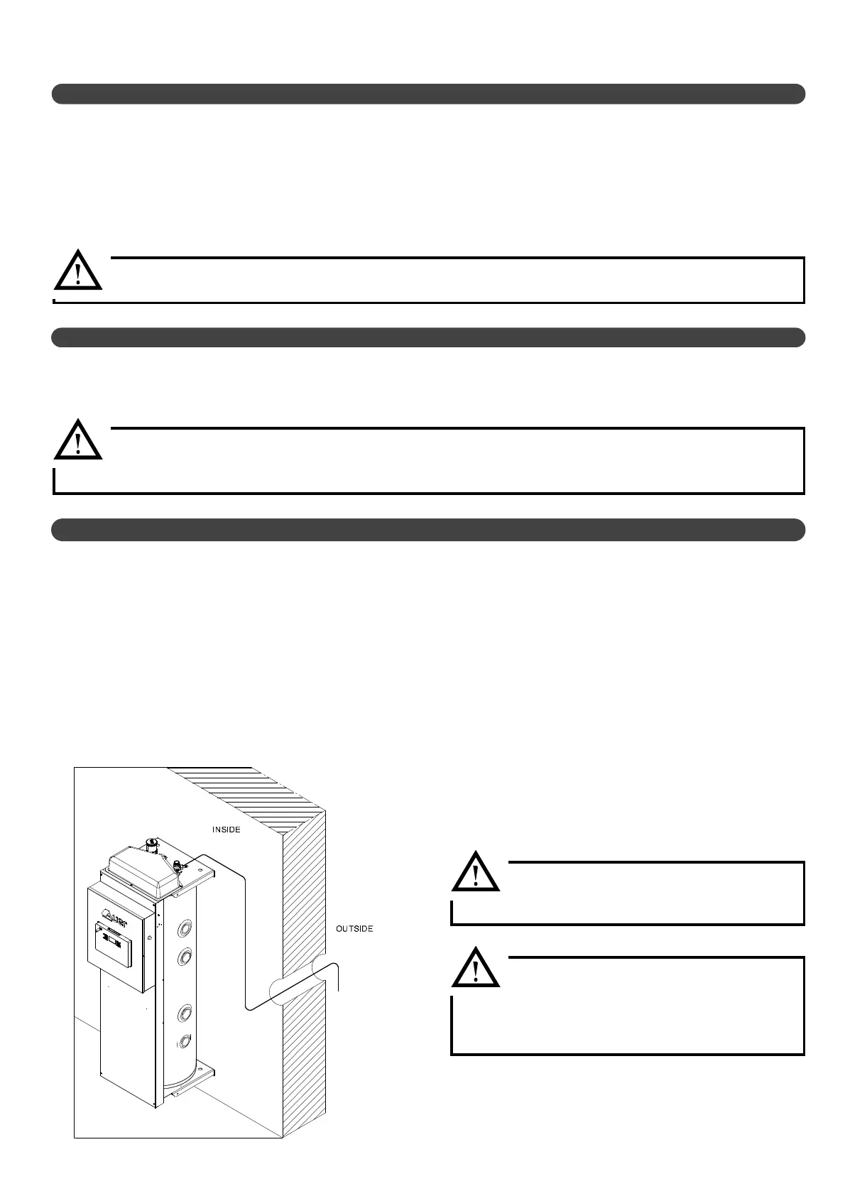
For safety reasons (potential presence of ammable R290 gas), drainage of the Pilot’s pressure-relief valve must MANDATORILY be done
outside the building. The outlet of the drainage pipe (4m length provided with the pilot) must be placed downwards in order to avoid any
introduction of water inside, any risk of obstruction due to frozen water or any other pollution (see drawing).
If the provided drainage pipe is too short, it’s mandatory to use a well-adapted length (can by supplied on demand). It will have to be installed
as well as there will be no pinch on it, it will then ensure the drainage of the overpressure from the 3 bar safety valve outside the building.
4.2.1.12 - Connecting the pressure relief valve
The Pilot’s pressure-relief valve drainage pipe
must be properly secured until the outside of
the building without any pinching zone.
WARNING
Failure to comply with this requirement
concerning the evacuation of overpressure outside
the building releases the heat pump manufacturer
from any liability in case of incident.