- 6P10 PILOT MANUAL
-
14
4.3 - Electrical connections
4.3.1 - Power electrical connections
• During the transport, an accidental
loosening of the electrical connections can
occur.
• In order to eliminate any risk of anomalous
overheating, a control of the tightening of the
connections is strongly recommanded.
See § «Spare parts list - electrical boxes»
The rules and regulations in the country of
installation MUST be respected (standard
C15-100).
• The electrical lines for general power supply to
the circuits must be made in compliance with your
country’s current rules and regulations (standard
C15-100).
• Standard C15-100 determines the cable section to
be used based on acceptable currents.
• Standard C15-100 determines the cable section to
be used based on the following elements:
- Nature of the conductor :
. type of insulation, number of strands, etc...
- Installation mode :
. in uence of conductor and cable groups
. ambient temperature
. tightly or non-tightly installed
. length of cables, etc...
4.3.3 - Power electrical connection of the pilot
Electrical supply must be protected by an omni-polar power cut-
o device having a 3mm minimum spacing (EN 60335.1) : fuses or
circuit breakers must be calibrated according to the power of the
pilot.
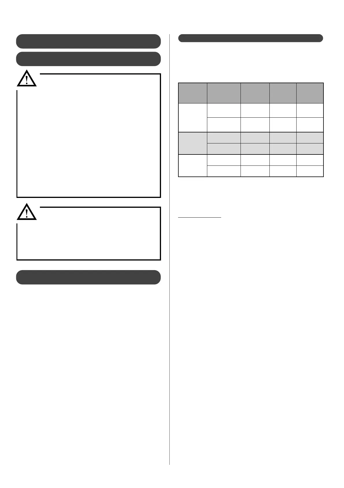
Electrical protection - 6P10 (with electrical back-up)
Number of
circulator
pumps
Supply
voltage
Cable cross-
section
Maximum
intensity
called
Circuit
braker
2
230V mono
3 G 6 mm² to
3 G 10 mm²
27,9 A 32 A
400V tri
5 G 2.5 mm²
to 5 G 4 mm²
9,3 A 16 A
3
230V mono 6 to 10 mm² 28,7 A 32 A
400V tri 2,5 to 4 mm² 9,5 A 16 A
4
230V mono 6 to 10 mm² 29,4 A 32 A
400V tri 2,5 to 4 mm² 9,8 A 16 A
Plan for a circuit breaker dedicated to the power supply of the Pilot
on the electrical panel. It must be able to completely cut-o the
electrical supply from the network (all-pole) to eliminate any danger
when carrying out maintenance on the appliance.
How to proceed:
• Check that the «ground» cable is connected properly to the
grounding peg or grounding network of the building.
• Connect the Pilot’s electrical cable to the dedicated plug,
equipped with a circuit breaker.
• Leave the pilot switched o until set-up.
• If a back-up boiler has to be connected ensure it is powered
o before any action.
The proper voltage is: 230 V (+10% / -15%).
Each appliance is delivered from the factory completely pre-wired.
However, it is necessary to connect the following elements to the
relevant terminals:
• The general electricity supply.
• The di erent sensors or thermostats on the Pilot.
• The 2-core shielded cable connecting the Pilot and the Heat
pump (10m length supplied).
• The back-up boiler (optional)
For three phase 400V electrical connection, refer to § «Electrical
Power Connection»
Under no circumstances will the manufacturer be held liable for
any problems which may arise due to improper installation and/or
choice of power supply cable.
4.3.2 - Prior recommandations before power
electrical connections
Check:
• The power consumption
• Number and thickness of the power supply
cables
• Fuse or circuit breaker ratings
The power supply must come from an electrical protection and
sectioning device which complies with all current rules and
regulation in e ect in the country of use.
This CE-approved unit complies with all the essential requirements
of the following directives:
- Low voltage n°2006/95/CE
- Electromagnetic compatibility n° 2004/108/CE
Ensure that the installation is equipped with a properly sized and
connected grounding cable.
Ensure that the voltage and frequency of the general power supply
ts requirements.
The acceptable variation in voltage is:
230 V -10% to +6% 50Hz for single-phase + Ground models.
400 V -10% to +6% 50Hz for three-phase + Neutral + Ground models
Under no circumstances will the manufacturer be held liable for
any problems which may arise due to improper installation and/or
choice of power supply cable.
Electrical supply of each device must be done power off by a
quali ed professional.