- 6P10 PILOT MANUAL
-
12
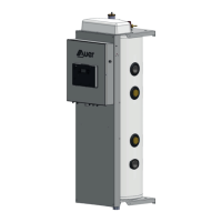
As a reminder, depending on your installation, it is possible to rotate
the pilot’s bu er tank to place 1 to 6 plumbing ttings on the right
and 7 to 10 ones on the left :
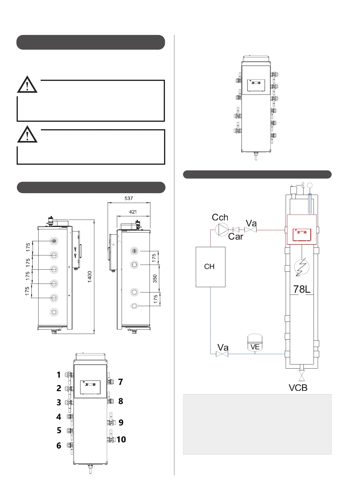
4.2.2.1 - Back-up boiler connection
CAR : Check valve
Cch : Boiler circulator pump (controlled by the boiler)
CH : Boiler
Sch : Boiler pressure relief valve
VA : Stop valve
VCB : Desludging valve
VE : Expansion vessel
4.2.2 - Hydraulic connections
1’’1/2 plumbing ttings apart from drain valve (1’’1/4).
Left side Right side
• Clean the lter at least once a year.
4.2.1.13 - Filter on the water inlet of each
heat pump (supplied)
It is mandatory to install the 1’’ 1/4 lter with incorporated 500μm
lter on the water inlet pipe of each heat pump :
• Mind the ow direction of the lter. (arrow).
Clean the lter several times when the
circulator pump of each heat pump is
working for the rst time. (do not forget to stop the
circulator pump of each heat pump when cleaning).
• It is mandatory ti install the 500μm lter
provided with the heat pump to prevent the
heat pump’s exchanger from clogging.
• Before heat pump(s) hydraulic connections, you
have to desludge and to rince the installation.