- 6P10 PILOT MANUAL -
15
4.3.4 - Power connection of the HRC
70
heat
pump
It is mandatory to read the installation manual
provided with each HRC
70
heat pump.
The terminals connection are «Cage Clamp» terminals spring.
For Handling, use the following :
- for 2.5mm² or 4mm² control terminals, use a
3.5 x 0.5mm at-head screwdriver.
- for 6mm² power terminal, use a 5.5 x 0.8mm
at-head screwdriver.
- for 10mm² power terminal, use a 5.5 x 0.8mm
at-head screwdriver.
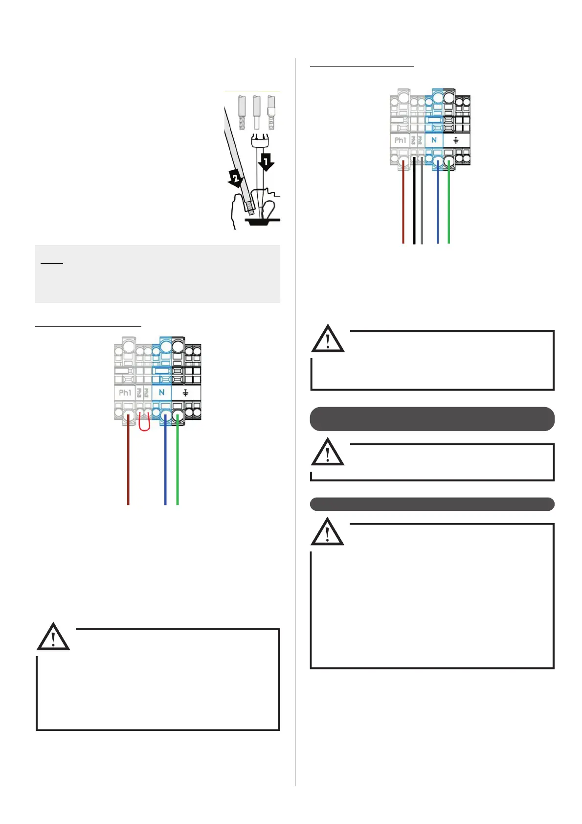
1 : Insert the screwdriver into the rectangular
window located on top of the terminal block.
2 : Insert the wire ito the «Cage Clamp» when the
ap is open.
3 : Remove the screwdriver.
Note : The wires must be stripped to the following lengths :
- For 2,5mm² control terminals : between 10 et 12mm
- For principal powers terminals : between 18 et 20mm
- For intermediate powers terminals : between 11 et 13mm
4.3.5 - Control connection of the heat pump
• Distance between the pilot and the heat
pump must not be higher than 100m
• In order to avoid disruptions related to the values
of the sensors read by the controller, control and
power lines must be wired independently. Avoid
junction boxes.
• Conductors must be made of electrolytic copper.
• Telephone wire use is forbidden.
• Control cross-section cables must be between
0,5 and 1mm².
Single phase power supply :
• Connect the power supply to the main terminal block on the power
board. Use only the Ph1 terminal (brown wire below above) for
phase connection.
• Make sure that the internal cable between the Ph1 terminal and
the Power Electronics Board (red cable) is connected to the last
terminal (marked P3) of the power board.
The phase must be connected to the Ph1
terminal on the main terminal block,
which in connected to the P3 terminal
on the power board with the red internal
cable.
Make sure these connections are followed
before powering on.
Three phase power supply :
• Connect the power supply to the main terminal block on the power
board. Each phase must be connected to one of the terminals P1,
P2, P3 (remove the bridge between terminals P1 and P2).
• Remove the X2 and X3 connector bridges.
Do not power up without rst checking
that the connectors X2 and X3 and the
bridge between terminals P1 and P2 have
been removed.
Terminal block