- 6P10 PILOT MANUAL -
28
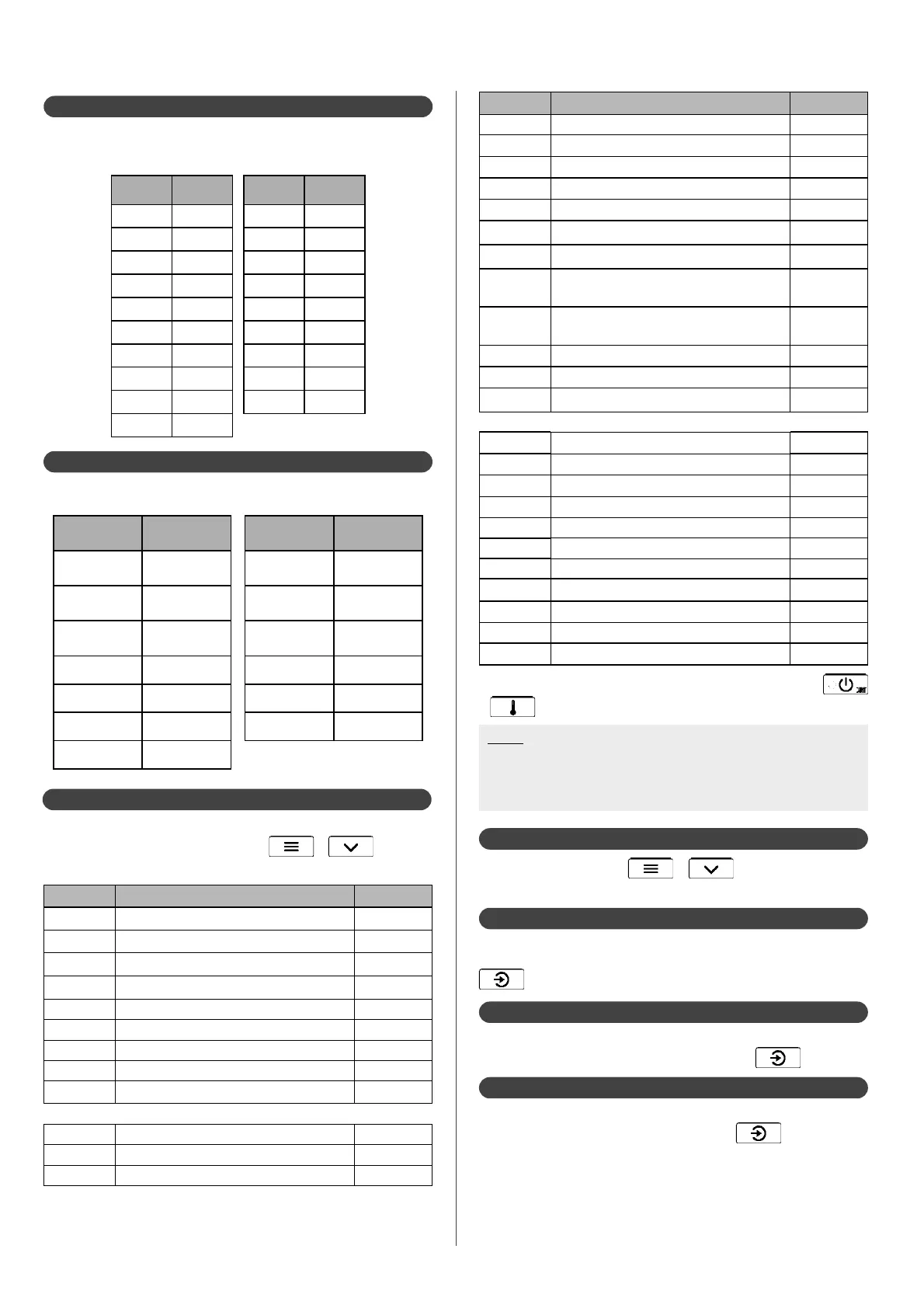
7.1.3 - Water sensors
Ohmic values for T_pilote (pilot outlet) and T_water (domestic
water sensor placed in the tank) sensors
T (°C) R (ohms) T (°C) R (ohms)
0 32 550 50 3 605
5 25 340 55 2 990
10 19 870 60 2 490
15 15 700 65 2 084
20 12 490 70 1 753
25 10 000 75 1 481
30 8 060 80 1 256
35 6 535 85 1 070
40 5 330 90 915
45 4 372
10
1 à 25°C
7.1.4 - Exterior sensor
Ohmic values for OUTSIDE (exterior) sensor
T (°C) R (ohms) T (°C) R (ohms)
-30 171 800 5 28 600
-25 129 800 10 22 800
-20 98 930 15 18 300
-15 76 020 20 14 770
-10 58 880 25 12 000
-5 45 950 30 9 804
0 36 130
12
1 à 25°C
7.1.5 - Consulting the counters
To consult the pilot and heat pump counters, enter the Expert
menu by pressing simultaneously on
+ , and
select the COunters sub-menu.
Counter n° Description Unit
C-00* Time of DHW request from tank h
C-01* Time of heating request from ambience (circuit n°1) h
C-02* Time of heating request from ambience (circuit n°2) h
C-06* Time of heat pump operation h
C-07* Time of boiler heating request h
C-08* Stage 1 Operating Time of the electrical back-up h
C-09* Stage 2 Operating Time of the electrical back-up h
C-10* Stage 3 Operating Time of the electrical back-up h
C-11* Defrosting cycles quantity
HEAT PUMP
C-20 Heat pump operating time h
C-21 Number of start-ups from compressor n°1 quantity
C-22 Number of start-ups from compressor n°2 quantity
Note :
If several heat pumps are connected, each of them will have its
own counters, readable via HP1, HP2, HP3 sub-meus in COUNTERS
menu.
* counters which can be reset to zero by long pressing (5s) on
+ in the counters menu.
Counter n° Description Unit
C-23 Operating time of compressor n°1 h
C-24 Operating time of compressor n°2 h
C-25 Defrosting cycles quantity
C-26 Frequent defrosting errors quantity
C-27 High pressure (switch) on compressor n°1 quantity
C-28 Activation of high pressure switch for compressor n°2 quantity
C-29 Activation of low pressure switch for refrigerant uid quantity
C-30
Activation of high temperature for compressor n°1
exhaust
quantity
C-31
Activation of high temperature for compressor n°2
exhaust
quantity
C-32 Overheating at heat pump outlet quantity
C-35 Insu cient ow rate quantity
C-36 BUS error quantity
PILOT
C-40 Time of DHW request from tank h
C-41 Time of heating request from ambience (circuit n°1) h
C-42 Time of heating request from ambience (circuit n°2) h
C-45 Time of heating request for back-up boiler h
C-46 Stage 1 Operating Time of the electrical back-up h
C-47 Stage 2 Operating Time of the electrical back-up h
C-48 Stage 3 Operating Time of the electrical back-up h
C-49 Overheating at pilot outlet error quantity
C-50 Lack of water pressure error quantity
C-51 Lack of water pressure defect quantity
C-52 Error loss of BUS connection quantity
Activate the forced operation of the circulator pump to check that
circulation is working properly. To activate forced operation press
.
7.1.6.1 - Circulator pump
Activate (always in the manual menu of the pilot) the forced
operation of the electrical back-up by pressing
.
7.1.6.2 - Electrical back-up
Activate (always in the manual menu of the pilot) the forced
operation of the Back-up boiler by pressing
.
7.1.6.3 - Back-up boiler
7.1.6 - Manual forcing of components
Enter the Expert menu ( + ) and then the manual
sub-menu.