- 6P10 PILOT MANUAL -
17
4.4 - Connection of circuits and accessories
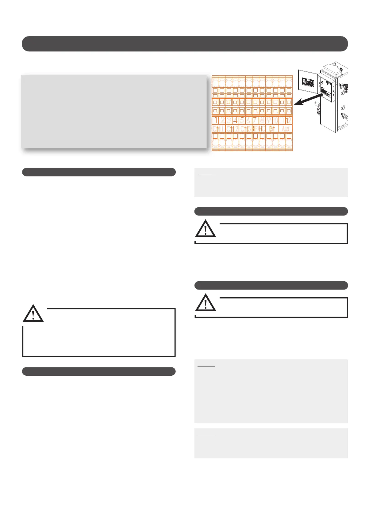
Sensors and accessories details :
1-2 = Zone 1 control (ambience thermostat or water tank sensor )
3-4 = Zone 2 control (ambience thermostat or water tank aquastat)
5-6 = Zone 3 control (water tank sensor)
7-8 = Peak hours contact
9-10 = Outdoor sensor
11-12 = Back-up boiler command (To connect to the thermostat input
of the boiler)
In an installation with both thermostatic valves and a room
temperature thermostat, the radiator(s) in the room in which the
thermostat is located
MUST be equipped with a manual valve(s).
It is mandatory to install the ambient temperature control on an
interior wall of the room and not a wall that lets out onto the outside
of the building.
Installation against an exterior facing wall is prohibited.
Do not place the ambient temperature controller too close to a
window, a curtain, or a door. Avoid placing it in an alcove, a closet,
or behind drapes.
Do not place above a heat source (radiator,...)or against a wall with
a chimney.
Do not place in reach of sun’s rays, or near powerful lighting.
Place the sensor 1.50m above oor level, and at least 50cm away
from neighboring walls. Insulate the extremeties of the electrical
cabling of the installation on the side of the appliance to prevent
air currents from in uencing the measures taken.
EXCLUSIVELY connect the AMBIENT
TEMPERATURE RADIO THERMOSTAT
(Ref.770001).
All other thermostats which are
chronoproportional may cause malfunctioning
and render the warranty null and void.
4.4.1 - Room thermostat
The connection of the exterior sensor is recommended (if it is not the
heat curve is calculated using the temperature read by the air sensor).
Place the sensor on the coldest exterior wall of the building (usually
the north-facing wall). It must not be exposed to the morning sun.
It is preferred to mount the exterior sensor in the middle of the wall of
the building or of the heating zone, at least 2.5m above ground level.
Do not place the sensor:
- above windows, doors, air exhausts, or other heat sources,
- beneath balconies or gutters
To prevent mistakes in the temperatures measured due to air
circulation, insulate the extremities of the sensor’s electrical conduit.
Do not paint the exterior sensor.
4.4.2 - Exterior sensor
Note :
After connection, go to the «DISPLAY» menu and check that the
«EXTERIOR» screen appears with the value read by the probe.
If not, check the connection of the probe or the pilot connector.
4.4.4 - Domestic water sensor
EXCLUSIVELY connect the water sensor
(Ref. 710029).
If DHW is produced by a domestic hot water tank:
- Place the sensor in the well of the tank to inspect the
temperature of the hot water immediately available.
- Connect the water sensor to the terminals of the Pilot.
4.4.3 - Domestic water aquastat
EXCLUSIVELY connect the water sensor
(Ref. 752202).
If DHW is produced by a domestic hot water tank:
- Place the aquastat bulb in the well of the tank to inspect the
temperature of the hot water immediately available.
- Connect the aquastat to the terminals of the Pilot.
Note1 :
For DHW tanks equipped with an aquastat, the setting of the
temperature target corresponds to the temperature of the tank
circulating in the exchanger. For DHW tanks equipped with a
water sensor, the setting of the temperature target corresponds
to the water temperature in the tank.
If the water temperature is controlled by aquastat, the
temperature target set to the pilot must be 5°C to 10°C higher
than the temperature target set to the aquastat.
Note2 :
The thermostat (in the case of a heating circuit) or the aquastat
(in the case of a DHW circuit) connected to terminals 1 and 2 must
be able to withstand a voltage of 230V.