- 6P10 PILOT MANUAL
-
9
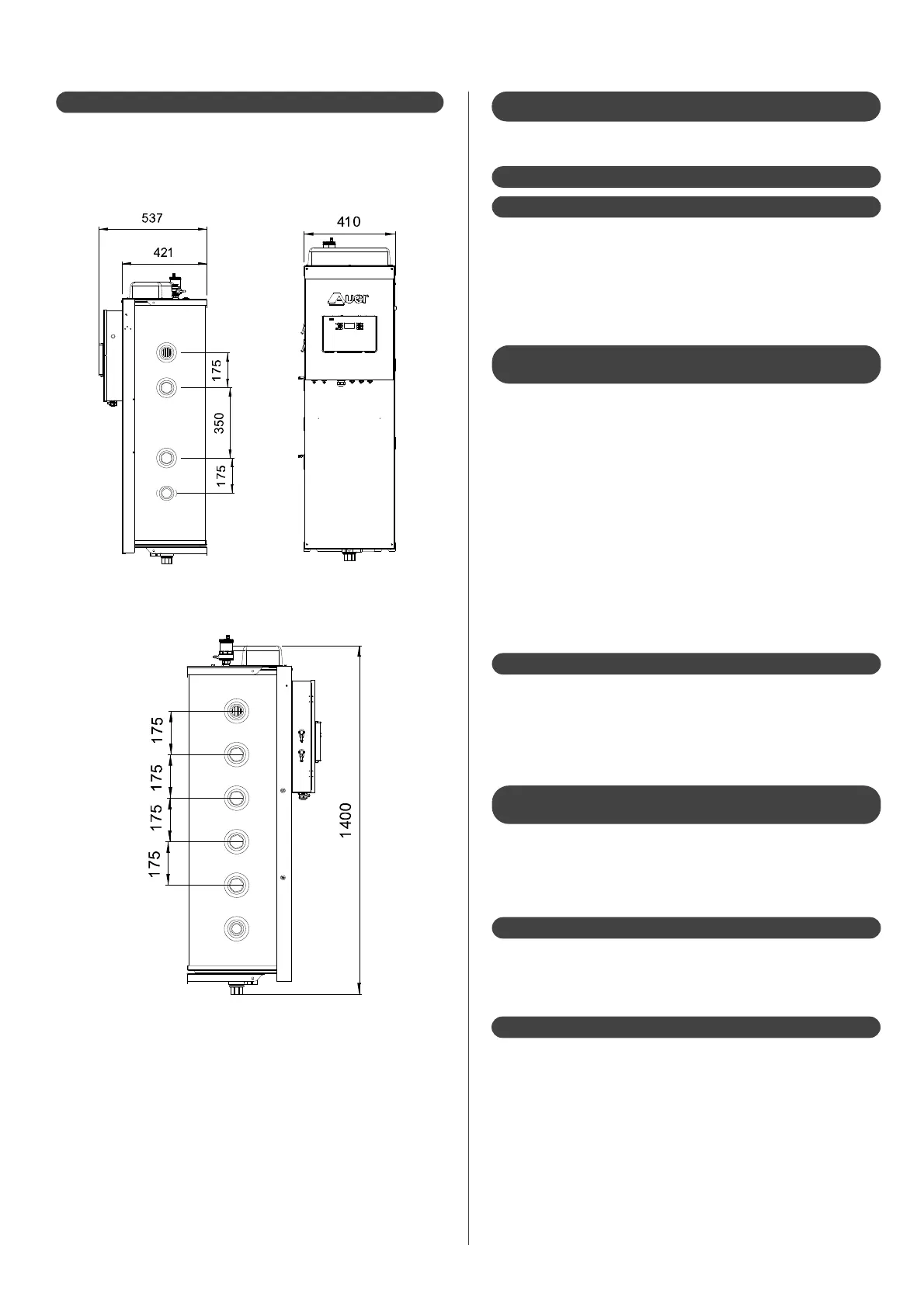
4.1.3 - Dimensions
The pilot must be placed at least 200mm above the oor or any
obstacle the enable it to be drained.
It must be placed at least 400mm under the ceiling to facilitate
the access to the air bleed and to the electrical back-up.
4.2.1 - Recommendations
A type CB backflow prevention device may be installed. This
device must be at di erent, non-regulated pressure zones. Check
your national laws and regulations to know if this is an obligatory
requirement. The backflow prevention device is designed to
prevent incoming heating water from entering the drinking water
circuit. It must be connected to the mains drainage system.
4.2.1.1 - Back ow prevention device
A su cient ow rate should be ensured so that the di erence in
temperature between the outlet and inlet points does not exceed
6°C. In an installation equipped with thermostatic mixing valves, this
inspection must be done with all taps/valves open.
The output actually needed determines the water ow rate of
the heating circuit and allows to calculate the dimensions of the
distribution network.
Adapt the speed of the circulator pump to the hydraulic
characteristics using the ow rate/pressure curve provided.
All necessary measures must be taken to ensure that the installation
can be continuously purged. Automatic air purging valves should be
placed at each high point of the installation, and manual air purging
valves should be installed on each radiator.
4.2.1.2 - Cross sections, purging of the
heating circuits
4.2 - Hydraulic installation
Consult the hydraulic schematic diagrams in the appendix.
Plan for a desludging tank with a su icient volume at a low point
on the inlet of the heating circuit. This tank must be equipped
with a drain so it can collect the oxides, particles, and calamines
which detach from the inner walls of the heating circuit while it is
in operation.
4.2.1.3 - Desludging tank
Before placing the pilot and heat pump, it is necessary to rinse the
installation with an appropriate product. This allows to eliminate all
traces of soldering waste, joint ller, grease, sludge, metallic particles,
etc... in the radiators, under oor heating, etc...
4.2.1.4 - Preparing the hydraulic circuit
(rinsing)
4.2.1.5 - Insulation of the pipes
Insulators must be in accordance with DTU 67.1.
All the apparent pipes and accessories (circulator, expansion vessel,
valve, ...) must be insulated or placed in insulated box.
4.2.1.6 - Expansion vessel
The installation must be equipped with an expansion vessel with
a su cient capacity (which depends on the static height of the
installation, the blowing-up pressure of the expansion vessel and
the volume of the installation)