- 6P10 PILOT MANUAL
-
8
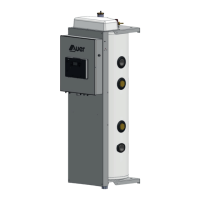
1. 78L bu er tank
2. Heat pump circulator pump
(except for HRC
70
40kW)
3. Distribution circuit
circulator pump
4. 6kW electrical back-up
5. Electronic control
6. Power electronic card
7. Distribution circuit
8. Drain
9. Heat pump circuit
3.5 - Operating principles
4 - INSTALLATION
4.1 - Placement choice
4.1.1 - Appropriate placement choice
The Pilot must be placed in an area which is free from frost and
adverse weather conditions.
It must be placed as close as possible to the heat pump without
exceeding the maximum distance.
The maximum distance depends on the diameter of piping and the
number of elbows used (see «Hydraulic connection» tables).
The 2-core sheathed cable which connects the Pilot and the heat
pump is 10m long. There is a 20m length available as an optional
extra (Ref. 753102) or 50m (Ref. 754103).
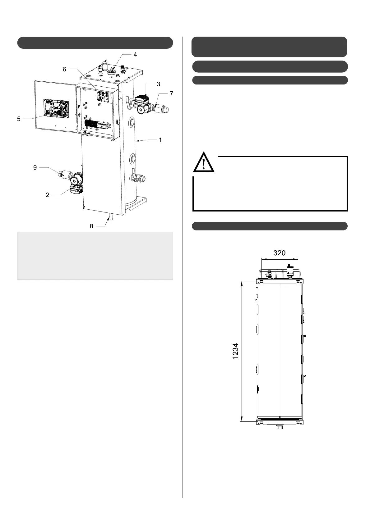
The Pilot must be installed on a level
and stable base which is distanced from
appliances used for cooking and other heat
sources.
The Pilot lled with water can be heavy, watch
over the resistance of the wall stand.
The pilot must be xed on a resistant wall.
4.1.2 - Fixation