- INSTALLER HIGHTEMPERATURE ENERGY EFFICIENT HEAT PUMP MANUAL -
14
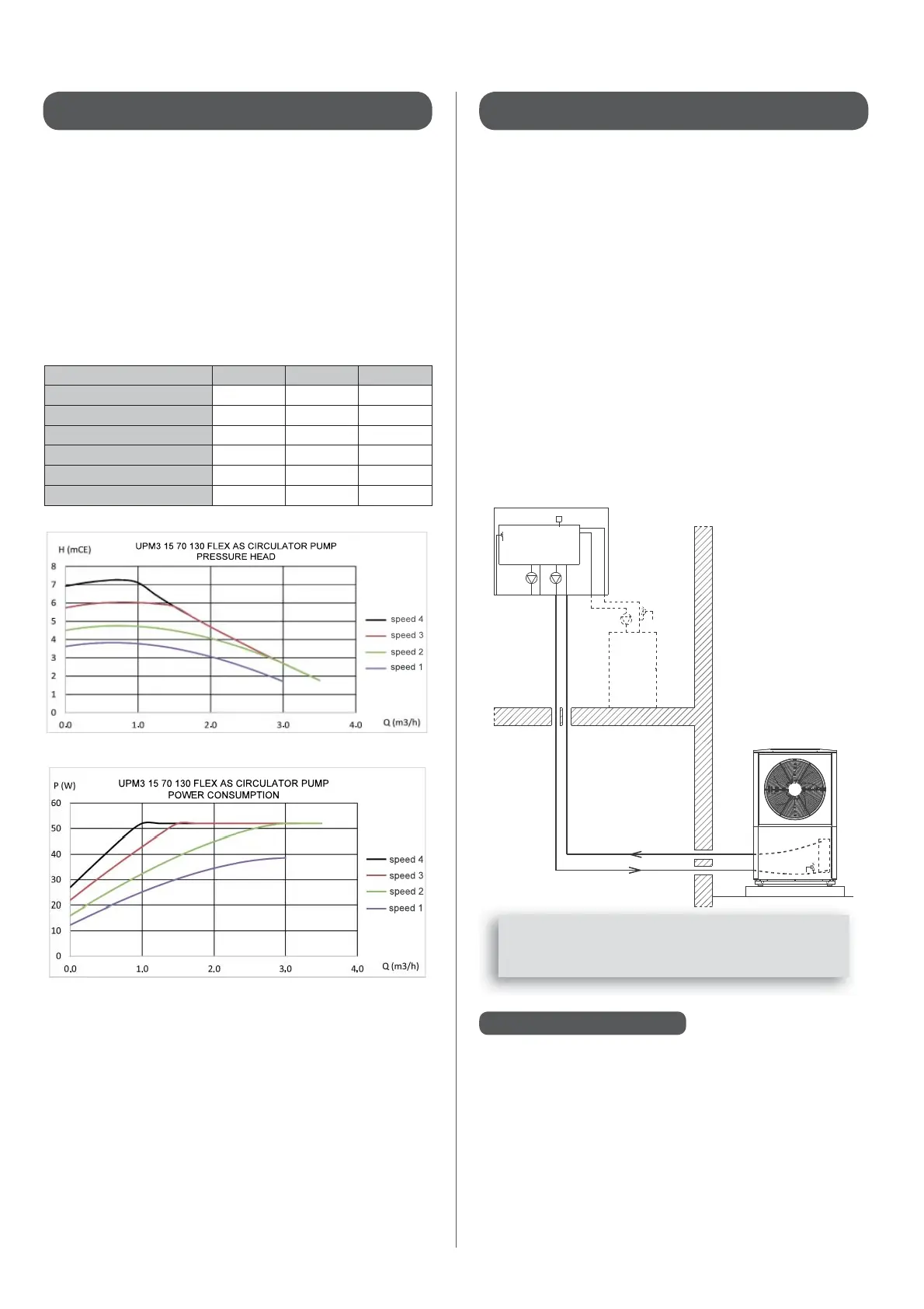
3.2.2 - Hydraulic connection : Heat Pump circuit 3.2.3 - Heat Pump and Pilot relief valve
3.2.4 - Desludging
When the heat pump is running at full power the ow rate
must be high enough to ensure that the temperature di erence
between the outgoing and incoming water is no greater than 5°C
(take a temperature reading when the HRC
70
is in heating mode
and the system is fully functioning).
The hydraulic connection section between the Heat Pump and
the Pilot must be su cient.
Using the tables below, determine the minimum inner diametre
of the connection piping needed depending on the distance
which separates the Heat Pump from the Pilot:
Heat pump model 17kW 20kW 25kW
Minimum nominal flow rate 1350 L/h 1550 L/h 1850 L/h
Maximium pressure 2.5 bar 2.5 bar 2.5 bar
minimum piping Ø
if distance* between HP and control < 15m 24/26 28/30 32/34
if distance* between HP and control < 25m 28/30 32/34 36/38
if distance* between HP and control < 50m 32/34 36/38 42/44
* distance com
rises full circuit
Make sure that all sections of piping are tted with functional and
accessible air valves.
The hydrualic connection between the Heat Pump and the Pilot
can be made using steel, copper or PEX piping with a diametre of
at least 1’’.
The hydraulic kit must be tted using exible piping on the water
inlet and outlet points of the Heat Pump in order to prevent any
vibrations being transmitted to the heating system.
The Heat Pump and the Pilot are both tted with a pressure relief
valve.
The pressure relief valve on the Heat Pump sets the maximum
acceptable pressure in the installation (2.5 bars when hot). The
maximum service pressure on the Heat Pump must, consequently,
be lower than 2.5 bars.
Example : If the Heat Pump is positioned 5m below the Pilot , the
pressure reading on the Pilot would be 0.5 bars less than the
real pressure of the water in the Heat Pump. In this case, the
maximum pressure for the Pilot would be 2 bars.
Therefore it would be advisable to ll the heating circuit at
an intermediary pressure (between 1 and 1.5 bars).
In case of operating with boiler back-up these relief valves
MUST
be tted in addition to the ones which the boiler is already
equipped with.
The connections and evacuation conduits for the pressure relief
valves must be made from materials which are resistant to high
temperatures and corrosion.
PS : Pilot pressure sensor
RV : Pressure relief valve for Pilot, set at 3 bars
BRV : Pressure relief valve for existing boiler
HPRV : Pressure relief valve for Heat Pump set at 2.5 bars
The Pilot has an integrated desludging function which collects
oxides, scale and other particles which become detached from
the inner walls of the heating circuit. The lower part of the system
is equipped with a sludge valve which should be brie y activated
once a year (see § "Maintenance and Repairs").
For under oor heating installations, we would advise you to t
a settling tank, which will complement the actions taken by the
Pilot.
HRC Pilot
PS
RV
BPV
Existing
boiler
HRC Heat Pump
HPRV
See § ‘‘Setting the 4 speeds on the circulator pump’’ in appendix
1895709.
 Loading...