- INSTALLER HIGHTEMPERATURE ENERGY EFFICIENT HEAT PUMP MANUAL-
67
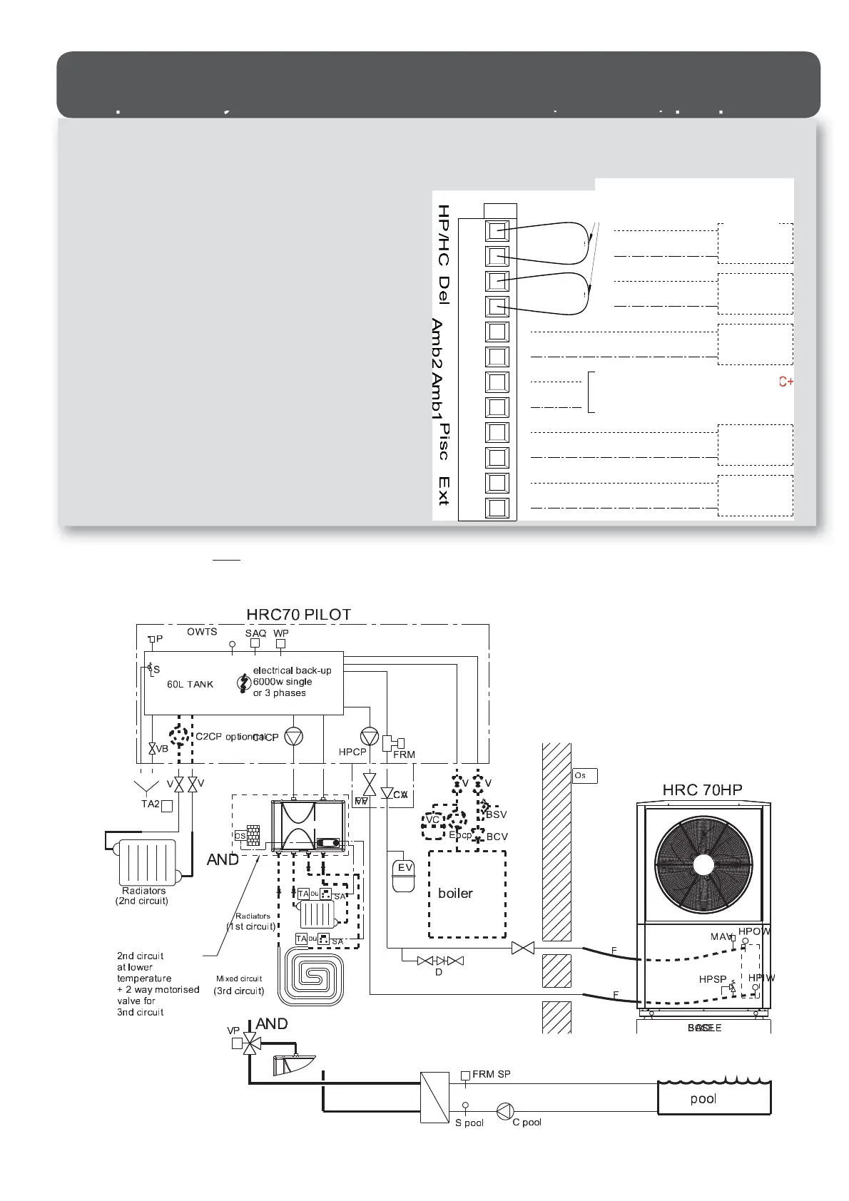
Hydraulic schematic diagram -2 DIRECT CIRCUITS and 3
rd
MIXED CIRCUIT -
with an optional 2
nd
circuit at a lower temperature (Ref.751014)
and optional 2-way motorised valve for 1st direct circuit (Ref. 740022) -pool possible-
HPCP = heat pump circulator pump
C1CP = heating circuit 1 circulator pump
C2CP = heating circuit 2 circulator pump (optional)
FRM = heat pump ow rate monitor
S = 3 bar safety valve
P = air valve
PTS = HRC
70
Pilot temperature sensor (or OWTS)
SAQ = safety aquastat with manual reset at 110°C
WP = water pressure sensor
SRV = sludge removal valve
FV = heat pump circuit lter valve
V = stop valves
CV = check valve (to be used if HRC
7O
Pilot is installed on a lower level than
the heat pump to avoid a thermosiphon e ect)
EV = expansion vessel
BPD = back ow prevention device
F = exible hose for heat pump connection
MAV = manual air valve
HPSV = heat pump safety valve set to 2.5 bar
HPIWS = heat pump incoming water temperature sensor
HPOWS = heat pump outgoing water temperature sensor
EBCP = existing boiler circulator pump
EVE = expansion vessel for existing installation
BSV = existing boiler safety valve
OS = Heat pump HRC
70
Pilot outdoor temperature sensor
RT1 = Heating circuit 2 room thermostat (optional)
UTL 1 = temperature-limiting safety device if circuit 1 is under oor heating
circuit (optional)
FRM SP = swimming pool ow rate monitor
S pool = swimming pool temperature sensor (included in swimming pool kit)
C pool = pool circuit circulator pump
3WV = 3-way valve for radiator circuit (winter) or pool circuit (summer)
BCV = boiler check valve
RT or RTS = room thermostat or room temperature sensor on 2
nd
circuit at a lower
temperature ‘Thorix Evolution’
On the P : • The 2
nd
circuit (RADIATOR C-2) or (UNDERFLOOR C-2), which must be the same kind as the rst circuit connected
to the Pilot, must be activated.
• Activate the room thermostat input (THERMOSTAT A-2) on the second circuit in order to monitor heat pump
operation using the on / o alert output on the Thorix Evolution (set P219 = 1 on the Thorix Evolution)
Remove red bridges when
connecting
PT/OP
LS
RTS2
(Load shedding)
Red
Red
On/o alert on Thorix TXC+
(with parametre P219=1)
S.POOL
OS