- INSTALLER HIGHTEMPERATURE ENERGY EFFICIENT HEAT PUMP MANUAL -
20
3.5.1 - Recommendations for connecting the
system to the power supply
3.5.2 - Connecting the Pilot to the power
supply
N.B: See electrical diagram in the appendix.
Check:
• The input current
• The number and thickness of power cables
• Fuse or circuit breaker ratings
The power supply must come from an electrical protection
and sectioning device which complies with all current rules
and regulations. This CE-stamped appliance complies with the
essential requirements of the following directives:
- Low voltage n°2006/95/CE
- EMC n° 2004/108/CE
Check the the installation is equipped with a correctly sized and
connected ground cable.
Check that the voltage and frequency of the general power
supply t requirements. The amount of variation in voltage
permitted is:
230 V -10% à +6% 50Hz for single phase models + ground cable
400 V -10% à +6% 50Hz for three-phase models + neutral + earth
cable.
The Pilot must be protected beforehand by an
all-pole circuit
breaker
(minimal distance to separate contacts = 3mm: EN 60
335-1) using either fuses or a thermal magnetic circuit breaker
calibrated to the right power for the Pilot.
Type of back-up
Without
back-up
or boiler
back-up
Power supply voltage
230 V mono 230 V mono 400V tri
Current absorbed
2 A 30 A 10 A
Fuse calibration for mains
switch
(1)
32 A 32 A 12 A
Power supply by phase
(2)
2.5 mm² min.
to 4 mm² max.
Number of conductors
(2)
4x2.5 mm² + T
(*)
min.
to 4x4 mm² + T
(*)
max.
(2)
The figures given here are indicative. They should be checked, and if necessary
adjusted, depending on the installation conditions and current standards.
(*)
The width of the ground cable should be equal to the width of the largest cable
6 kW electrical back-up
Pilot
6 mm² min.
to 10 mm² max.
2x6 mm² + T
(*)
min.
to 2x10 mm² + T
(*)
max.
(1)
or general bipolar or tetrapolar circuit breaker
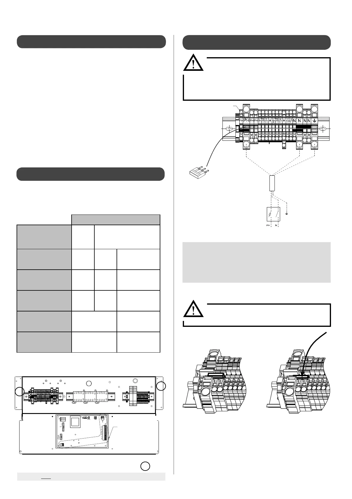
To access the terminals, remove the front faceplate of the Pilot
and open the control box by removing the two screws (
1
).
1
1
The HRC
70
Pilot is set for 400Vthree-phase
use.
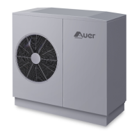
For 230V single phase use, you will need to t a
bridge (supplied in a small package) between the
three phase terminals. See diagram below.
Make sure the bridge is properly pushed
into place. See below:
PH-N : Phase/Neutral 230V single phase - 50Hz power supply
CPAC : Heat Pump circulator pump, pre-connected
Cchauf 1 : Circulator pump for heating circuit1
ou Pisc or primary pump for swimming pool circuit
Cchauf2 : Circulator pump for heating circuit 2
ou ECS Primary circulator pump for domestic water circuit
LTP1/LTP2 : Temperature-limiting safety aquastat (65°C) with manual reset. It must be
placed at the start of the under oor heating circuit (not supplied).
3.5.2.1 - Pilot: 230V single phase connection
Swimming pool option terminal
Main power
terminal
3 command terminals
on the
electronic board:
- 12 point (HP/HC; DEL;
Amb2;
Amb1; Pisc; Ext)
- 2 point (shielded
connection)
- 2 point (Chaud)
L1, L2 and L3 markings, to be
replaced by PH, PH and PH
Bridge to be tted for 230V
single phase use
3-wire section
to be de ned.
See table § 3.3.2
Fuse or thermal-magnetic
circuit breaker
230V MONO 50Hz
POWER SUPPLY
INCORRECT CORRECT