- INSTALLER HIGHTEMPERATURE ENERGY EFFICIENT HEAT PUMP MANUAL-
63
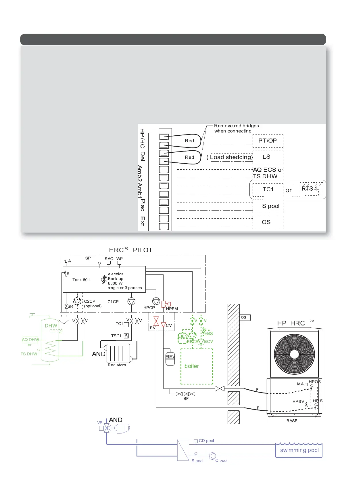
Hydraulic schematic diagram -1 RADIATOR CIRCUIT/ + DHW- -pool possible-
HPCP = Heat Pump circulator pump
C1CP = heating circuit 1 circulator pump
FRM = Heat Pump ow rate monitor
SV = 3-bar safety valve
P = air valve
PTS = HRC
70
Pilot temperature sensor (or outgoing water (OW)
temperature sensor)
SA = safety aquastat with manual reset, 110 °C
WP = water pressure sensor
SRV = sludge removal valve
FV = Heat Pump circuit lter valve
V = stop valves
CV = check valve (to be used if HRC
70
Pilot is installed on a lower level
than the Heat Pump to avoid a thermosiphon e ect).
EV = expansion vessel
BPD = back ow prevention device
F = exible hose for Heat Pump connection
MAV = manual air valve
HPSV = Heat Pump safety valve, set to 2.5 bar
HPIWS = Heat Pump incoming water temperature sensor
HPOWS = Heat Pump outgoing water temperature sensor
EBCP = existing boiler circulator pump
EVE = expansion vessel for existing installation
BSV = safety valve for existing boiler
OTS = Heat Pump HRC
70
Pilot outdoor temperature sensor
TC1 = heating circuit 1 room thermostat
or RTS1 = room temperature sensor with display for heating
circuit 1(optional)
or RTS2 = room temperature sensor for heating circuit 2
(optional)
AQDHW = Heating circuit 2 aquastat
DHWS = Heating circuit 2 DHW temperature sensor
(optional)
FRM SP = Swimming pool ow rate monitor
S pool = Swimming pool sensor (optional, included in
swimming pool kit)
C pool = swimming pool circulator pump
3WV = 3-way valve for radiator circuit (winter) or swimming pool circuit
(summer)
BCV = boiler check valve
DHW = DHW tank with >40kW heat exchanger