- INSTALLER HIGHTEMPERATURE ENERGY EFFICIENT HEAT PUMP MANUAL -
38
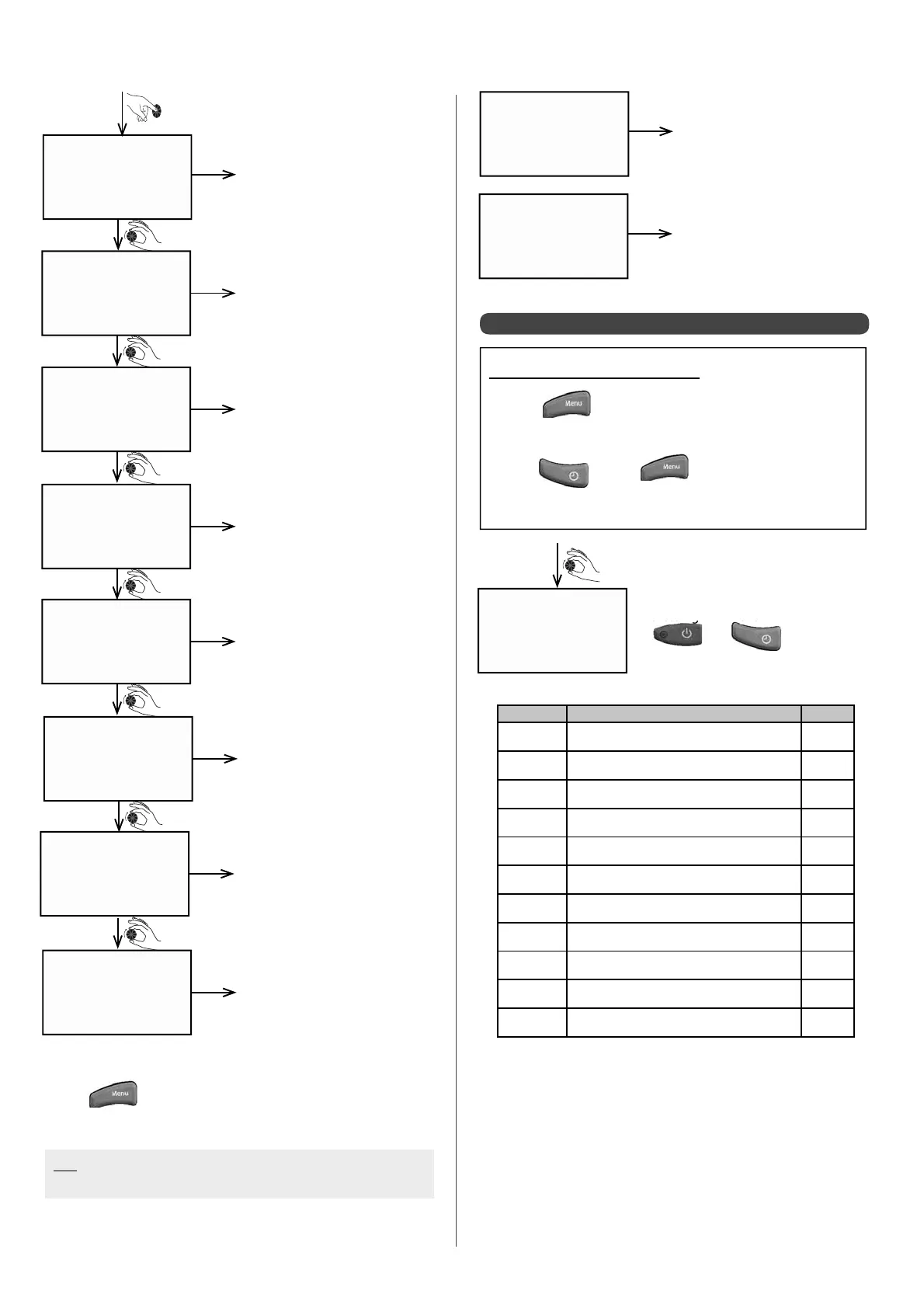
Trr COMP 1
00:07
h
TSR COMP 1
00:03
h
Tsr COMP 2
00:03
h
TRS COMP 1
00:03
h
Trs COMP 2
00:03
h
tmod COMP 1
00:04
h
tmod COMP 2
00:09
h
Trr COMP 2
00:04
h
Time period between 2 start-
ups for compressor 1
Minimum stopping time for
compressor 1
Minimum stopping time for
compressor 2
Minimum running time for
compressor 1
Minimum running time for
compressor 2
Time delay before compressor
1 engages
Time delay before compressor
2 engages
Time period between 2 start-
ups for compressor 2
example
example
example
example
example
example
example
• Press at any time to return to the data cALC. screen.
N.B: If 2 circuits are con gured, the heating curve is displayed
for each circuit
heat curv1
62.0 °C
Circuit 1 target temperature at
Heat Pump inlet (if 2 circuits)
example
heat curv2
57.0 °C
Circuit 2 target temperature at
Heat Pump circuit (if 2 circuits)
example
6.5.3 - Accessing the meters
Accessing the Installer Menu:
• Press
• Turn the dial until the screen displays
"INST. MENU"
• Press and at the same time
• Keep them held down simutaneously for 3 sec.
counters
Parametres 1 to 13 can be reset by
pressing down the
and
keys
simultaneously for 5 seconds:
Meter Function Unit
1
Zone 1 heating request hour
2
Zone 2 heating request hour
3
Heating request for zone 1 as pool hour
4
Heat pump operation
at least 1
ower sta
e functionin
hour
7
Compressor 1 operation hour
8
Compressor 2 operation hour
9
Boiler back-up request hour
10
Electrical back-up operation stage 1 hour
11
Electrical back-up operation stage 2 hour
12
Electrical back-up operation stage 3 hour
13
De-icing cycles number