- INSTALLER HIGHTEMPERATURE ENERGY EFFICIENT HEAT PUMP MANUAL -
22
3.5.3 - Connecting the HRC
70
Heat Pump to the power supply
The HRC
70
Heat Pump is CE-marked. It complies with the French standard NF C15-100 and the European standards EN 61000-3-3 et EN 61000-
3-11, among others.
It is equipped with soft starters, which limit the start-up current to 45A for single phase and 60A for three phase.
The power supply cable should be carefully sized according to the following factors:
- maximum current
- the distance between the HRC
70
Heat Pump and the power
supply source
- overall protection
- the neutral operating system
Take care to strip the cable before pushing it into the
terminals, and make sure that the copper is in good
condition.
A means of disconnection must always be tted in compliance with the
installation rules.
If the power supply cable is damaged it must be replaced by a
suitably quali ed professional.
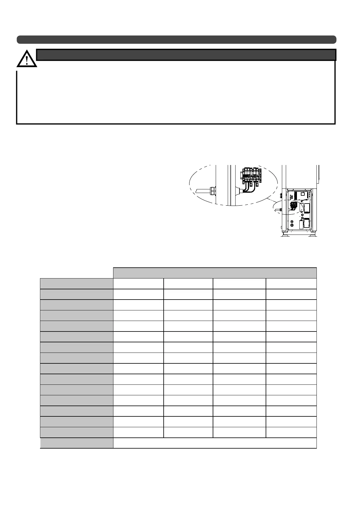
To access the terminals, remove the panel on the bottom left hand side (2
screws) and open the electrical box (8 screws).
The electrical power supply cable should rst be inserted through an exterior compression gland and then through a cable grommet on the
electrical box.
- It is the responsibility of the installer and the client to contact the electricity provider and ensure
that the appliance is compatible with the power grid before connecting the HRC
70
Heat Pump (see
the information form which is an appendix to this document).
- The power grid impedance value must be less than the Heat Pump impedance Z
max
(see § "Connecting the
HRC
70
Heat Pump to the power supply").
- If electrical installation standards are not respected, irreversible damage could be sustained to the HRC
70
Heat Pump, which will not be covered by the manufacturer’s warranty.
ELECTRICAL INSTALLATION RECOMMENDATIONS
HRC
70
heat pump model
HRC
70
17kW single phase
HRC70 17kW three phase HRC70 20kW three phase HRC70 25kW three phase
Power supply voltage
230 V single phase 400 V three phase 400 V three phase 400 V three phase
Maximum power consumption
6.5 kVA 6.5 kVA 7.5kVA 9 kVA
Maximum current requirements
35 A 13 A 15 A 18 A
Maximum start-up current
(1)
45 A 48 A 48 A 60 A
Compressor soft starter?
YES NO NO YES
Phi tangent when Heat Pump starts
up
Heat Pump (Zmax) impedance (ohm)
0.181 - - -
Phase impedance (Zmax) (ohm)
- 0.248 0.248 0.175
Neutral impedance (Zmax) (ohm)
- 0.166 0.166 0.117
Heat Pump regulation mode
Fixed speed Fixed speed Fixed speed Fixed speed
Number of power stages
33 2 3
Circuit breaker size
40A single phase 16A three phase 16A three phase 20A three phase
Power supply by phase
(2)
10 mm² 4 mm² 4 mm² 6 mm²
Number of conductors
(2)
2 x 10mm² + T
(*)
4 x 4mm² + T
(*)
2 x 10mm² + T
(*)
4 x 6mm² + T
(*)
(*) The width of the ground cable must be equal to the thickest part of the power supply cable.
(1)
D-curve bipolar or tetrapolar general circuit-breaker
(2) The figures given here are indicative. They must be checked and modified
if necessary according to conditions of installation and current rules and standards.
If the length of the cable exceeds 15m or if the network could be
subject to drops in voltage over 10V, use a thicker cable.
See ''Connecting the Pilot to the power supply'' table