- INSTALLER HIGHTEMPERATURE ENERGY EFFICIENT HEAT PUMP MANUAL -
16
3.3.1 - For radiator / fan coil unit circuits
3.3.2 - For under oor heating circuits
3.3.3 - For domestic hot water
3.3.4 - For swimming pools
3.3 - Installation advice for di erent
types of transmitters and di erent
uses
Thermostatic valves: these valves must primarily be used for
premises which receive high quantities of free calories from
sunlight. In an installation where only thermostatic valves are
used there
must be a bypass function in place (e.g. a di erential
valve).
In an installation with thermostatic valves and a room
temperature sensor, the room or area where the room
temperature sensor is located MUST have manual air valves tted
on the radiators.
In order to ensure full satisfaction from your room thermostat is
is essential to follow the installation and assembly instructions
when setting it up.
It is MANDATORY to t an under oor heating
temperature limiter on the outgoing water
point of each circuit.
As the domestic hot water can reach
temperatures of over 60°C (notably to protect
against legionellosis), a thermostatic mixing valve
MUST be tted onto the DHW outgoing point to
avoid risk of scalding.
Using a water tank where the primary heat
exchanger is around 25kW (1.5m²) can lead to
Heat Pump malfunction because of on / o cycles
which are too long.
It is not necessary to drain the tank.
• Adjust setting 207 to a value which is equal to or below 50°C (see
"Regulator settings").
• Replace the electrical bridges between terminals 4 and 5 for
circuit 1 and between terminals1 and 2 for circuit 2 used in the
under oor heating for the temperature limiters (UTL).
These aquastats cut o the power supply to the under oor
heating circulator pump on circuits 1 (
HPCP 1) and 2 (HPCP 2) in
case of abnormally high temperatures on the under oor heating
circuit.
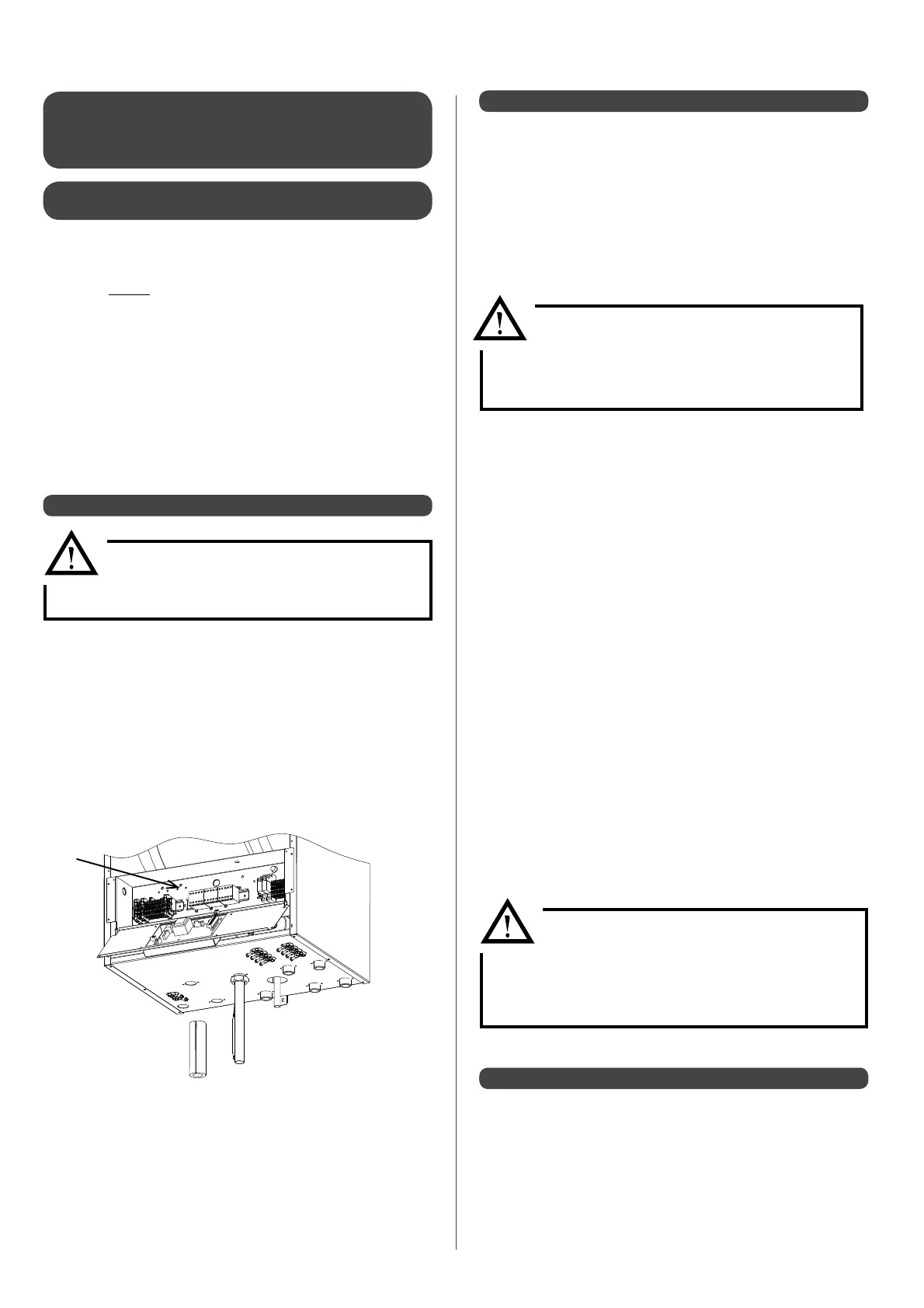
1 - Position the temperature limiter (UTL) at the desired point
2 - Place the bulb on the heating water outgoing water point pipe
3 - Use the clip to hold the bulb in place
4 - Fix the insulant around the bulb
5 - Remove the pre- tted
electrical bridges:
• between terminals 4 and 5 for circuit 1
• between terminals 1 and 2 for circuit 2
6 - Make the electrical connections for the under oor temperature limiter (UTL) on
terminals:
•4 and 5 for circuit 1
•1 and 2 for circuit 2
Place the safety aquastat on the pipe
at the outgoing water point
(example for circuit 1)
1
4
2
Domestic hot water can be produced by the Pilot. The hot water
tank is heated by a primary water circuit which is connected
to the Pilot (circuit 2)(Accessories : "2nd circuit at an identical
temperature"-Ref. 751003- and "DHW sensor" -Ref. 710029-).
It is important to equip the hot water tank with a
suitably powerful heat exchanger (minimum 40kW).
To ensure an e ective coupling with the Heat Pump the surface of
the water tank’s primary heat exchanger must be at least 1.5m².
For a non-permanent pool please refer to the instructions
provided with the control kit for summer pools (Ref. 751006).
THE CONTROL KIT FOR SUMMER POOLS MUST NOT
BE USED FOR A PERMANENT POOL SUMMER +
WINTER.
The domestic water circuit must be installed in compliance with
regulations and best practices. It is particularly important to
observe the following instructions:
• A pressure relief valve must be tted onto the cold water inlet on
the tank
• Do not t a shut-o valve between the pressure relief valve and
the tank.
NB : the pressure relief valve may let out a small amount of water
when the DHW is being reheated: this is normal.
• In order to prevent this run-o if the pressure exceeds 4 bars:
- Fit a pressure reducer on the cold water inlet
- Fit a DHW expansion vessel between the pressure relief
valve and the tank.
• The number of elbows used and drops in pressure must be
minimised, the plumbing xtures used must be
adapted to the installation.
• In regions where high levels of limescale are present in the water
(TH > 15), we would advise you to t an anti-scale
device on the cold water inlet. The TH should be under
15.
• The concentration of chloride in domestic hot water should be
less than 60mg/L (quality level required for drinking
water for human consumption).