7. Electrical connection Work on the electrical system or equipment must only be
carried out by a skilled electrician himself or by specially
instructed personnel under the control and supervision of
such an electrician and in accordance with the applicable
electrical engineering rules.
Installation regulations for DeviceNet must be observed for
the wiring (for literature references refer to appendix D).
7.1 Power supply (standard) For explosion-proof version (type designation: ACExC)
see page 17.
.
Check whether type of current, supply voltage and frequency correspond
to motor data (refer to name plate at motor).
.
Loosen bolts (50.01) (figure D-1) and remove connection housing.
.
Loosen screws (51.01) and remove socket carrier (51.0) from connection
housing (50.0).
.
Insert cable glands suitable for connecting cables.
(The enclosure protection stated on the name plate is only ensured if suit-
able cable glands are used).
.
Seal cable entries which are not used with suitable plugs.
.
Connect cables according to order-related wiring diagram.
The wiring diagram applicable to the actuator is attached to the
handwheel in a weather-proof bag, together with the operation instruc-
tions. In case the wiring diagram is not available, it can be obtained from
AUMA (state commission no., refer to name plate) or downloaded directly
from the Internet (www.auma.com).
7.2 Remote position transmitter For the connection of remote position transmitters (potentiometer, RWG)
screened cables must be used.
7.3 AUMATIC on wall bracket The AUMATIC can also be mounted separately from the actuator on a wall
bracket.
.
For the connection of actuator and AUMATIC on wall bracket, use suitable
flexible and screened connecting cables.
(Preconfectioned cables can be obtained from AUMA on request)
.
Permissible distance between actuator and AUMATIC amounts to a max.
of 100 m.
.
Versions with potentiometer in the actuator are not suitable. Instead of the
potentiometer, a RWG has to be used in the actuator.
.
Connect the wires in correct phase sequence.
Check direction of rotation before switching on.
Actuator controls AUMATIC AC 01.1 / ACExC 01.1
DeviceNet Operation instructions
14
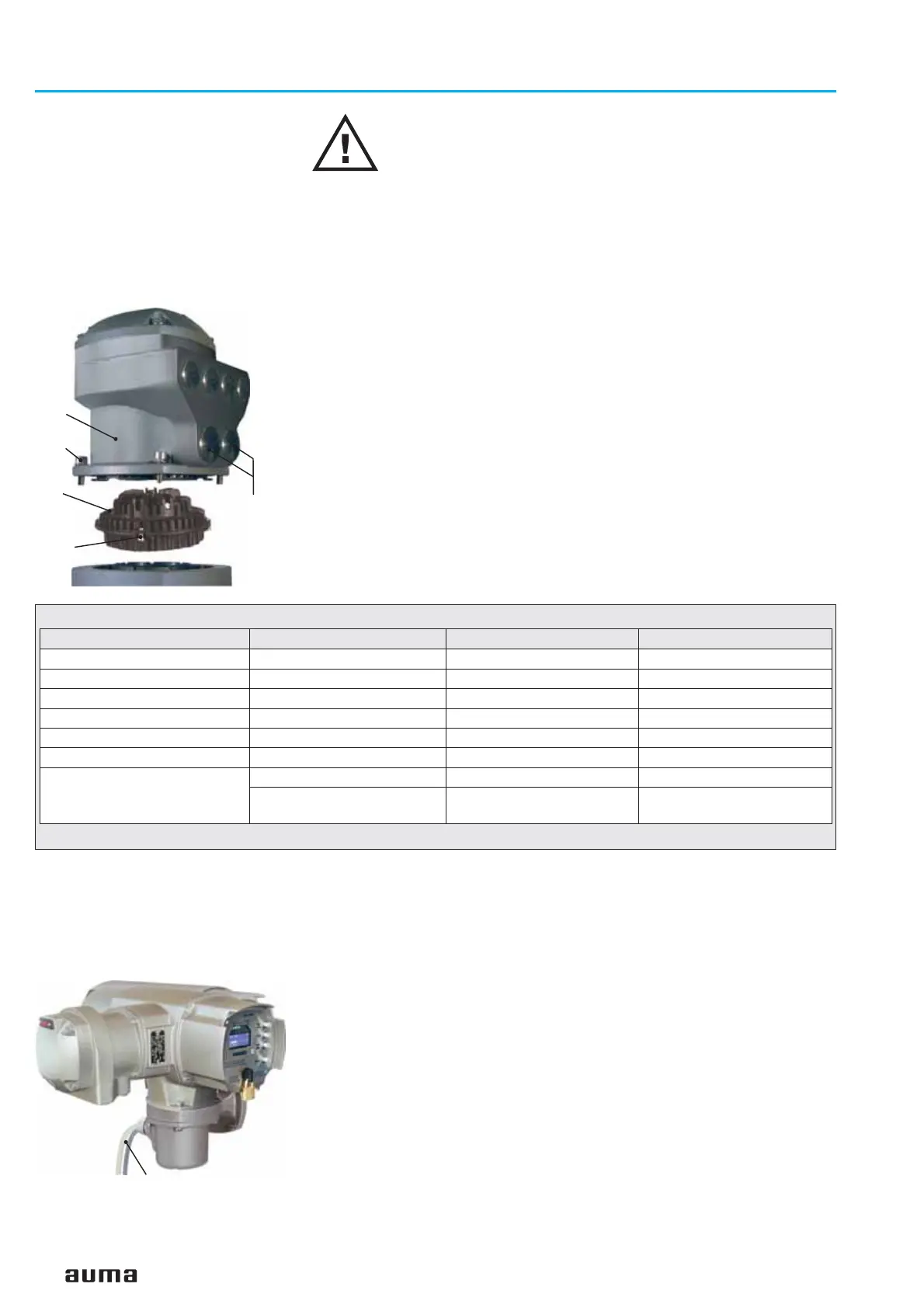
Figure D-1: Mains connection
50.0
50.01
51.0
51.01
Mains cable
Technical data Motor power connections
1)
Protective earth Control pins
No. of contacts max. 6 (3 are used) 1 (leading contact) 50 pins / sockets
Marking U1, V1, W1, U2, V2, W2 according to VDE 1 to 50
Voltage max. 750 V – 250 V
Current max. 25 A –
16 A
Type of customer connection Screws Screw for ring lug Screws
Cross section max. 6 mm
2
6 mm
2
2.5 mm
2
Material: Pin / socket carrier Polyamide
Polyamide Polyamide
Contacts Brass (Ms)
Brass (Ms)
Brass, tin-plated or
gold-plated (option)
1) Suitable for copper wires. For aluminium wires it is necessary to contact AUMA.
Table 4: Technical data AUMA plug/ socket connector for bus connection
Figure D-2: AUMATIC on wall bracket
Connection cable to the actuator

 Loading...


