The EMERGENCY function is defined via the parameters for the operation
mode EMERGENCY. Refer to the operation instructions to the actuator
(multi-turn actuator SA(R) … / part-turn actuator SG . . . with AUMATIC AC . . .).
If the actuator is to be operated via fieldbus or the inputs of the I/O, the selector
switch has to be in position “REMOTE”.
As soon as the EMERGENCY signal is no longer present (EMERGENCY input
at 24 V DC or 115 V AC as an option), operation commands which are trans-
ferred via DeviceNet are immediately executed, while OPEN/CLOSE operation
commands which are present at the additional control inputs are deleted and
have to be reapplied.
Note:
An automatic change-over to the I/O in case of an interruption of the bus
communication does not exist!
Feedback signals via AUMATIC display or via DeviceNet
16. EMERGENCY STOP function (option)
As an option, the AUMATIC can also be equipped with an EMERGENCY
STOP push-button. When engaged, this EMERGENCY STOP interrupts the
control voltage of the contactors.
Restrictions The EMERGENCY STOP function is not available for ACExC, but only for
the weatherproof versions of the AUMATIC
(enclosure protection IP 67 or IP 68).
Function As soon as this EMERGENCY STOP button is engaged, several steps are
performed in the AUMATIC.
.
The 24 V AC control voltage of the AUMATIC contactors is interrupted.
.
Switch-off of the operation command and cancelling of a possibly set
self-retaining.
.
Indication of the EMERGENCY-STOP status by setting a bit in the process
representation output (byte 9 – Not ready ind., bit 4 – Emcy STOP active).
.
Optional: Indication of the operation status of the EMERGENCY STOP
button by activating a signal relay.
.
Optional: Indication of the operation status of the EMERGENCY STOP
button by lighting up of a local control LED.
.
Indication of the EMERGENCY-STOP status in the display showing the
entry ‘EMCY STOP ACTIVE’ in the diagnosis page S3 “NOT READY IND.”
.
EMERGENCY STOP status indication in the status indication S0: Opera
-
tion status “EMERGENCY STOP”
45
Actuator controls AUMATIC AC 01.1 / ACExC 01.1
Operation instructions DeviceNet
Feedback signals on the display
DeviceNet Note
S3 NOT READY
IND.
EXTERNAL
CONTROL
Bit 13.7 = 1
(page 29)
Operation via parallel interface (i.e. BUS/REMOTE on 24 V
DC or optional 115 V AC)
EMERGENCY
MODE
Bit 13.5 = 1
(page 29)
Emergency mode is active (the EMERGENCY function is
active and 0 V are applied at the EMERGENCY input).
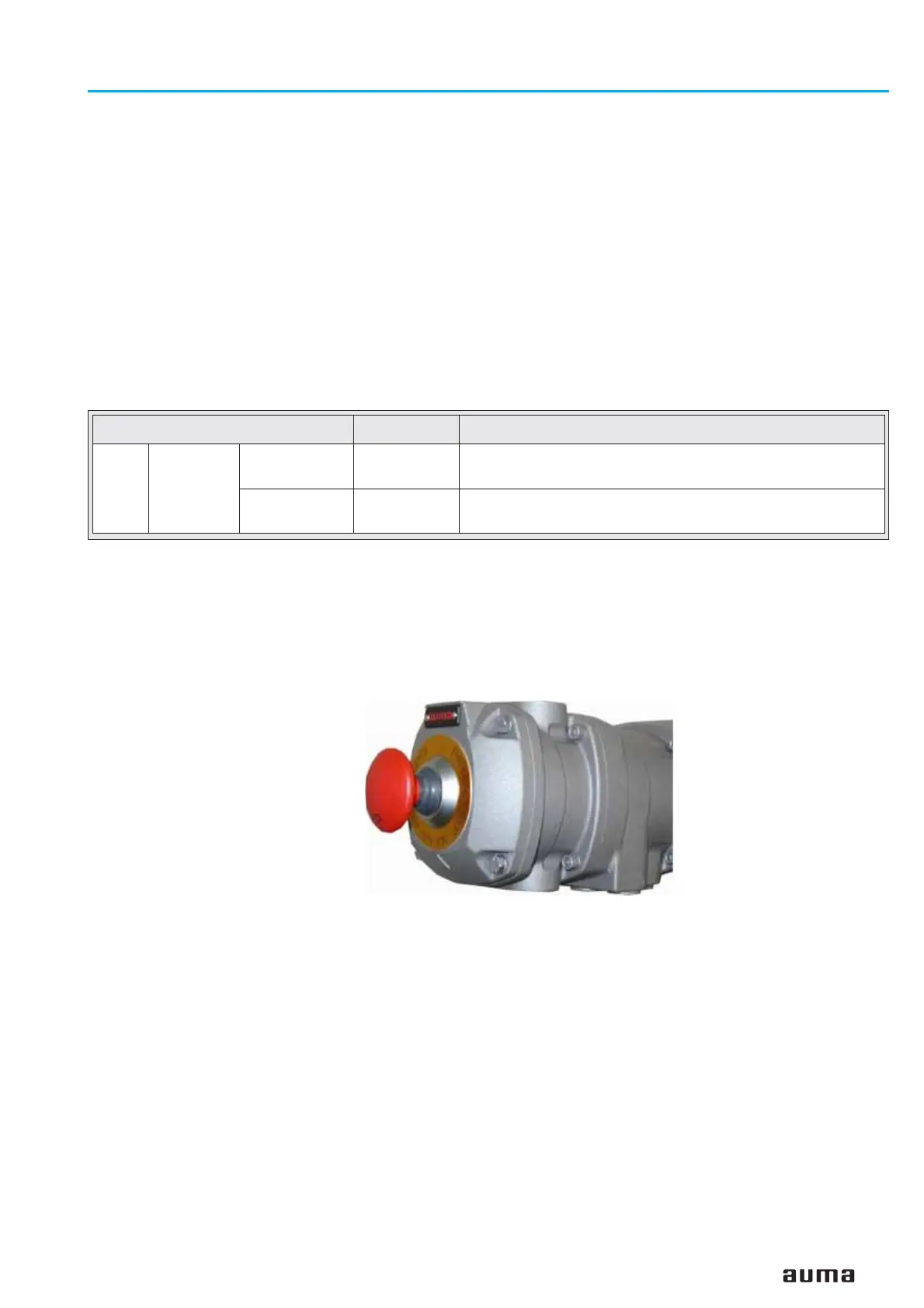
Figure L: AUMATIC with EMERGENCY STOP
mushroom button
 Loading...


