7.8 Mains and bus connection for explosion-proof version
When working in potentially explosive areas, observe the
European Standards EN 60079-14 “Electrical Installations in
Hazardous Areas” and EN 60079-17 “Inspection and Mainte-
nance of Electrical Installations in Hazardous Areas”.
Work on the electrical system or equipment must only be
carried out by a skilled electrician himself or by specially
instructed personnel under the control and supervision of
such an electrician and in accordance with the applicable
electrical engineering rules.
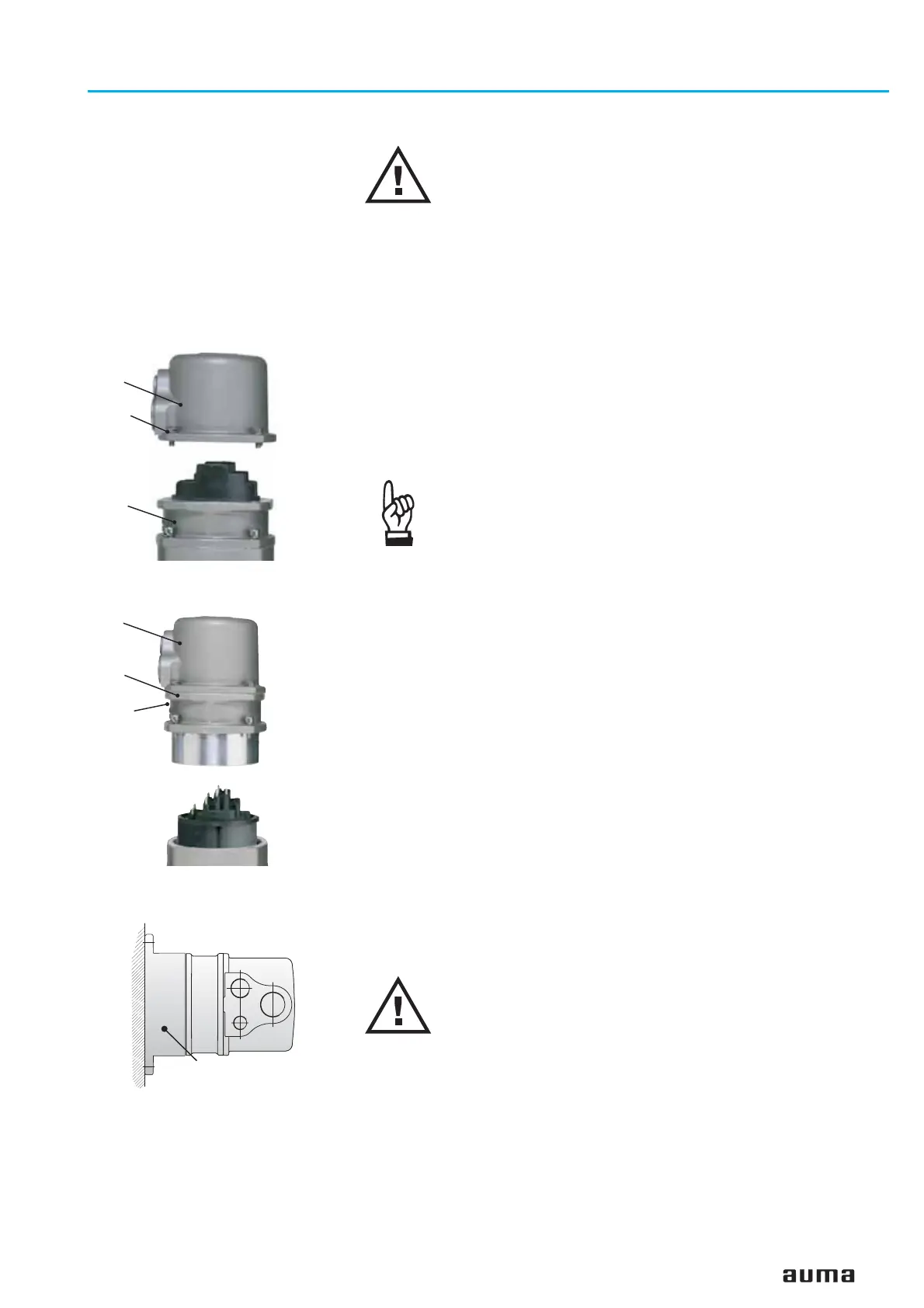
For the Ex-plug/socket connector (figure D-10), the electrical mains connec-
tion is made after removing the plug cover (50.0) at the EEx e terminals of
the terminal board (51.0). The flameproof compartment (type of protection
EEx d) remains hereby closed.
.
Check whether type of current, supply voltage and frequency correspond
to motor data (refer to name plate at motor).
.
Loosen bolts (50.01) (figure D-10) and remove plug cover.
.
Insert cable glands with “EEx e” approval and of size suit-
able for connecting cables. For the recommended cable
glands refer to appendix E, page 65.
(The enclosure protection stated on the name plate is only
ensured if suitable cable glands are used).
.
Seal cable entries which are not used with suitable plugs.
.
No more than max. 2 wires with the same cross section
may be connected to one terminal.
.
Remove cable sheathing in a length of 120 – 140 mm.
Strip wires: Controls max. 8 mm, motor max. 12 mm.
For stranded wires use end-sleeves according to DIN 46228.
.
Connect bus cable. Refer to figures (D-13 or D-14).
The termination resistor for channel 1 is connected through linking the
terminals 31 – 33 and 32 – 34 (standard).
The termination resistor for channel 2 is connected through linking the
terminals 47 – 37 and 48 – 38 (component redundancy only).
.
The termination resistor may only be switched on if the actuator is the last
bus station in the DeviceNet trunk line.
.
Connect screen largely to the threads. For the recommended cable glands
refer to appendix E, page 65.
If the actuator must be taken from the valve, e.g. for service purposes, it can
be separated from the mains without having to remove the wiring
(figure D-11). For that the screws (51.02) are removed and the plug/ socket
connector is pulled off. Plug cover (50.0) and terminal board (51.0) remain
together.
Flameproof enclosure! Before opening, ensure that there is
no explosive gas and no voltage.
A special parking frame (figure D-12) for protection against touching the
bare contacts and against environmental influences is available.
Actuator controls AUMATIC AC 01.1 / ACExC 01.1
Operation instructions DeviceNet
17
Figure D-10: Connection
50.0
50.01
51.0
Figure D-12: Parking frame
(accessory)
Parking frame
Figure D-11: Disconnection
from the mains
50.0
51.0
51.02

 Loading...


