15. Combination fieldbus / standard interface (option)
The AUMATIC can also be equipped with an additional interface. By this, an
additional operation command channel (digital inputs or an analogue
0/4 – 20 mA input) is available and furthermore, the available feedback
possibilities of the I/O interface (relay contacts, analogue feedbacks) can be
used, additionally to the feedback signals transmitted via fieldbus. Inde-
pendent of the signal assignment of these inputs, the fieldbus communica-
tion with the DCS will remain intact.
The settings for the I/O interface and the fieldbus interface are performed
via the following menus:
Menu structure
MAIN MENU (M)
SETTINGS (M1)
I/O 1 (M14)
DEVICENET 1 (M1M)
Standard application: Generally, the bus communication has priority, i.e. in case of unconnected
conventional inputs I/O inputs, the AUMATIC reacts only to operation
commands which are received by the fieldbus interface. At the same time,
the programmed feedback signals of the I/O interface (relay output and
analogue outputs) are available.
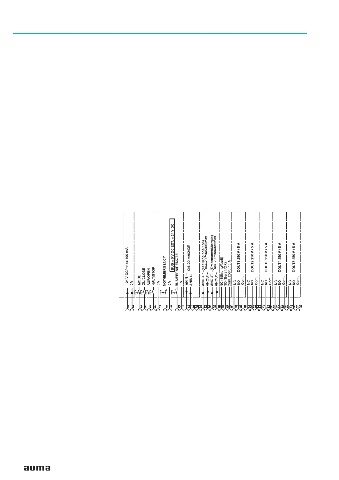
As soon as the ‘BUS/REMOTE’ (figure J-2) input is supplied with 24 V DC
(or 115 V AC), the AUMATIC will only react to operation commands which
are received via the I/O (OPEN-CLOSE or MODE and 0/4 – 20 mA nominal
value).
In case of an unconnected MODE input (or MODE input connected to 0 V),
the input signal of the analogue input 1 is interpreted as nominal position
signal. If the safety behaviour is accordingly programmed (see page 40), a
safety position can be approached, in case of interruption of the nominal
value signal (parameter:
FAILURE SOURCE = NOMINAL VALUE E1).
Application with EMERGENCY function active:
The EMERGENCY function has the highest priority. The polarity of the
EMERGENCY input is identical to the standard AUMATIC version (equipped
with an I/O interface). This means that the actuator will perform the
programmed EMERGENCY operation if 0 V is applied at the EMERGENCY
input (or the EMERGENCY input is unconnected) independently from the
“BUS/REMOTE” input and from the operation commands received via
fieldbus. As long as this EMERGENCY signal is present, the actuator can
neither be operated by the digital input signals of the parallel interface nor
via the fieldbus.
44
Actuator controls AUMATIC AC 01.1 / ACExC 01.1
DeviceNet Operation instructions
Figure K: Pin assignment with parallel interface (wiring diagram extract)

 Loading...


