14. Additional control inputs (option)
The digital and analogue input signals of the DeviceNet interface can be
interpreted as additional operation commands. Through this, an additional
operation command channel is available (four digital inputs or one analogue
0/4 – 20 mA input). Independent of the signal assignment of these inputs,
the fieldbus communication with the DCS will remain intact.
Menu structure
MAIN MENU (M)
CONFIGURATION (M4)
SETUP (M41)
EXTERNAL INPUTS BUS (M410G)
Possible settings of the parameter EXTERNAL INPUTS BUS:
STANDARD
The signals of the four digital inputs and the analogue inputs are transmitted
by the fieldbus to the process control system. They do not influence the
operation behaviour of the actuator.
OPEN CLOSE MODULATING DUTY
Conventional control of the actuator is both possible in OPEN-CLOSE duty
and in modulating duty (setpoint of 0/4 – 20 mA).
Generally, the bus communication has priority, i.e. in case of unconnected
I/O inputs, the AUMATIC reacts only to operation commands which are
received by the fieldbus interface.
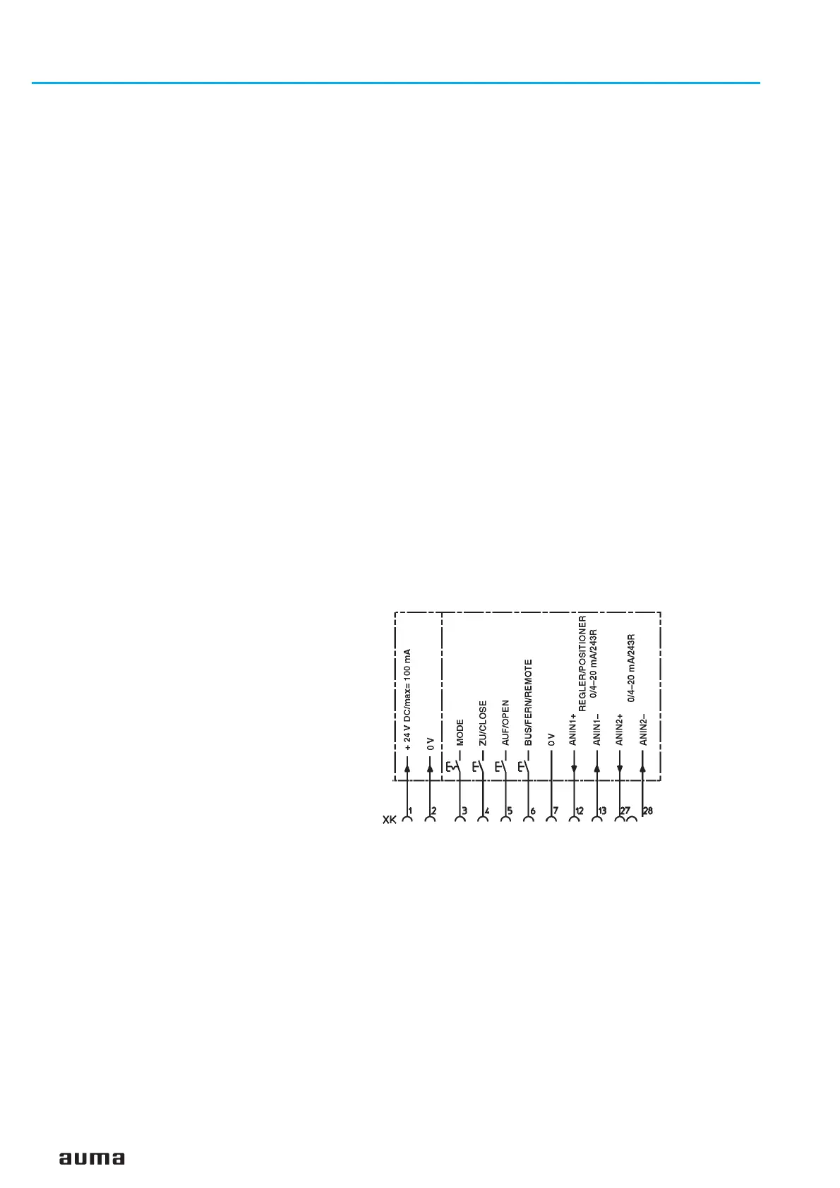
As soon as the ‘BUS/REMOTE’ input (figure J-1) is supplied with 24 V DC
(or optional 115 V AC), the AUMATIC will only react to operation commands
which are read in via these digital inputs (OPEN-CLOSE or MODE and
0/4 – 20 mA nominal value). Self-retaining is not available for the
OPEN – CLOSE commands.
In case of an unconnected MODE input (or MODE input connected to 0 V),
the input signal of the analogue input 1 is interpreted as nominal position
signal. The measuring range of this analogue input is programmable.
Furthermore, the safety function (see page 40) can be tripped in case a
signal loss of this setpoint signal was detected (Parameter:
FAILURE
SOURCE
= SETPOINT E1.).
For this function, the selector switch must be in position “REMOTE”.
42
Actuator controls AUMATIC AC 01.1 / ACExC 01.1
DeviceNet Operation instructions
Figure J-1: Pin assignment for OPEN–CLOSE–modulating duty
(wiring diagram extract)

 Loading...


