7.4 Fitting of the connection
housing
After mains connection:
.
Insert the socket carrier (51.0) into the plug cover (50.0) and fasten it with
screws (51.01).
.
Clean sealing faces at the connection housing and the actuator housing.
.
Check whether O-ring is in good condition.
.
Apply a thin film of non-acidic grease (e.g. Vaseline) to the sealing faces.
.
Replace connection housing (50.0) and fasten bolts (50.01) evenly cross-
wise.
.
Fasten cable glands with the specified torque to ensure the required
enclosure protection.
7.5 Test run Perform test run. Refer to the operation instructions to the actuator
(multi-turn actuator SA(R) … / part-turn actuator SG . . .
with AUMATIC AC . . .).
7.6 Check limit and torque switching
Check limit and torque switching, electronic position transmitter RWG or potenti-
ometer (option) and, where necessary, re-set.
The settings are described in the operation instructions to the actuator
(multi-turn actuator SA(R) … part-turn actuator SG . . . with AUMATIC AC . . . ).
For actuators with feedback signal (RWG, potentiometer), a reference oper-
ation has to be performed after the setting has been changed.
Perform reference operation:
.
Run actuator electrically (via the push-buttons OPEN and CLOSE) of the
local controls once to the end position OPEN and once to the end position
CLOSED.
.
If no reference operation is performed after changing the limit switching,
the feedback signal via the bus is not correct. The bus signals the missing
reference operation as warning (see page 29).
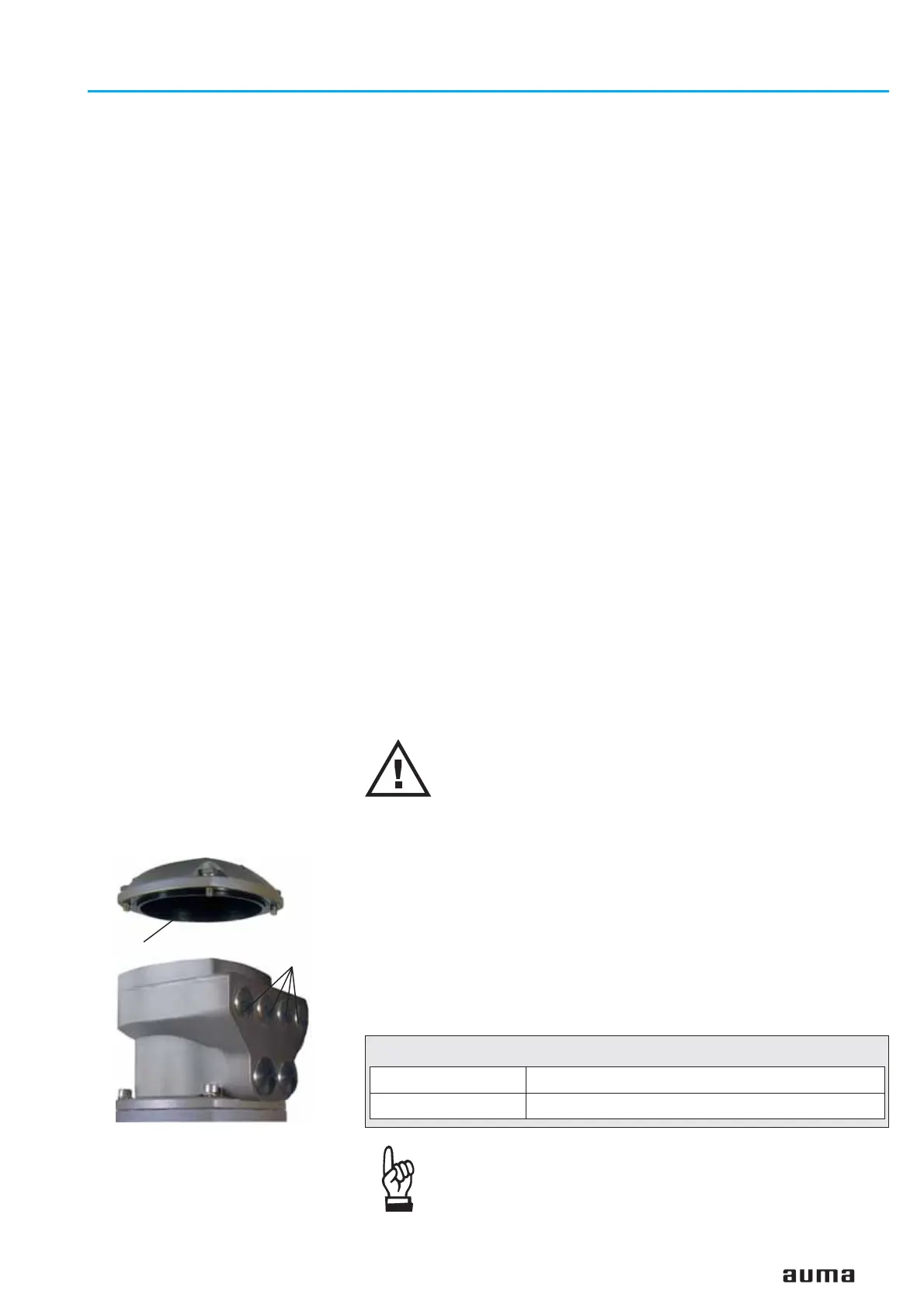
7.7 Bus connection (standard) For explosion-proof version (type designation: ACExC)
see page 17.
Disconnect power before removing the plug cover.
.
Loosen and remove plug cover (figure D-3). The connection board
(figures D-4, D-5 and D-8) is located behind the plug cover.
.
Insert cable glands suitable for bus cables.
(The enclosure protection stated on the name plate is only ensured if suit-
able cable glands are used).
.
Seal cable entries which are not used with suitable plugs.
.
Connect bus cable. See figures D-4 to D-9.
The termination resistor is switched on with the switch (S1/S2)
(figures D-4, D-5 and D-8).
The switch is supplied in position ‘OFF’. The termination resistor may only
be switched on if the actuator is the last bus station in the DeviceNet trunk
line.
The max. current load of the pins for the DeviceNet cable in
the electrical connection is 2.5 A. This has to be observed
when planning the DeviceNet topology (location of the
DeviceNet power supply, current consumption of the
connected DeviceNet devices).
Actuator controls AUMATIC AC 01.1 / ACExC 01.1
Operation instructions DeviceNet
15
Figure D-3: AUMATIC bus
connection
Plug cover
Entries for
bus cables
ON Bus termination switched on
OFF Bus termination switched off
Table 5: Switch position S1/S2

 Loading...


