Actuator controls AUMATIC AC 01.1 / ACExC 01.1
DeviceNet Operation instructions
16
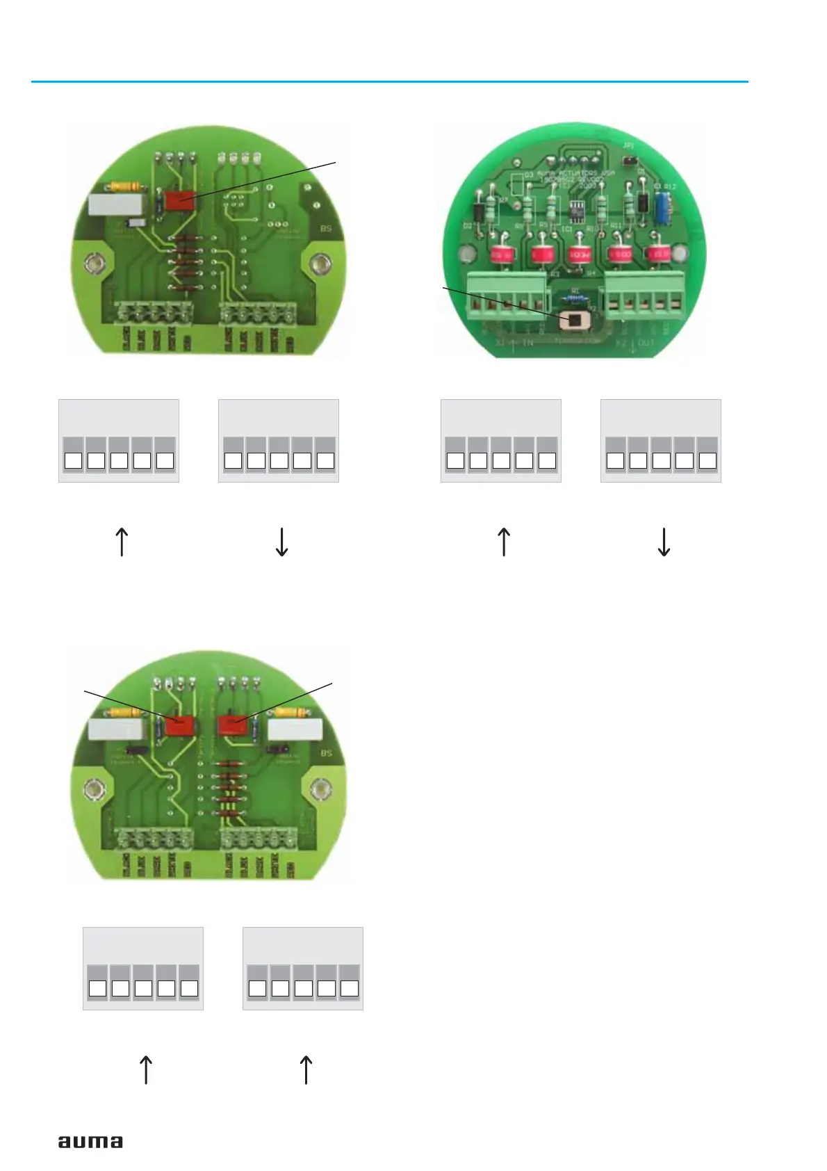
Figure D-5: Connection board (for overvoltage protection)
S1
Bus termination
Figure D-4: Connection board (standard)
S1
Bus termination
channel 1
X1 IN
BLACK
BLUE
BARE
WHITE
RED
X2 OUT
BLACK
BLUE
BARE
WHITE
RED
Figure D-7: Connection diagram (for overvoltage protection)
from previous
DeviceNet device
(thin or thick cable)
to next
DeviceNet device
(thin or thick cable)
X1 IN
BLACK
BLUE
BARE
WHITE
RED
X2 OUT
BLACK
BLUE
BARE
WHITE
RED
Figure D-6: Connection diagram (standard)
from previous
DeviceNet device
(thin or thick cable)
to next
DeviceNet device
(thin or thick cable)
Figure D-8: Connection board (for component redundancy)
S2
Bus termination
channel 2
S1
Bus termination
channel 1
X1 IN
BLACK
BLUE
BARE
WHITE
RED
X2 IN
BLACK
BLUE
BARE
WHITE
RED
Figure D-9: Connection diagram (for component
redundancy)
DeviceNet device
channel 1 (thin cable)
DeviceNet device
channel 2 (thin cable)

 Loading...


