OPEN CLOSE ESD
Conventional control is possible in the open-close duty
(OPEN-CLOSE-EMERGENCY). The analogue inputs ANIN1 and ANIN2
have no function.
In this configuration, the EMERGENCY function has the highest priority. The
polarity of the EMERGENCY input is identical to the standard AUMATIC
version (equipped with an I/O interface). This means that the actuator will
perform the programmed EMERGENCY operation if 0 V is applied at the
EMERGENCY input (or the EMERGENCY input is unconnected) independ-
ently from the “BUS/REMOTE” input and from the operation commands
received via fieldbus. As long as this EMERGENCY signal is present, the
actuator can neither be operated by the digital input signals of the fieldbus
interface nor via the DeviceNet.
The EMERGENCY function is set via the parameters for the operation mode
EMERGENCY. Refer to the operation instructions to the actuator (multi-turn
actuator SA(R) … / part-turn actuator SG . . . with AUMATIC AC . . .).
As soon as the EMERGENCY signal is no longer present (EMERGENCY
input at 24 V DC or 115 V AC as an option), operation commands which are
transferred via DeviceNet are immediately executed, while OPEN/CLOSE
operation commands which are present at the additional control inputs are
deleted and have to be reapplied.
For this function, the selector switch must be in position “REMOTE”.
OPEN CLOSE STOP
Conventional control is possible in the open-close duty
(OPEN-CLOSE-EMERGENCY). The analogue inputs ANIN1 and ANIN2
have no function.
Generally, the bus communication has priority, i.e. in case of unconnected
I/O inputs, the AUMATIC reacts only to operation commands which are
received by the fieldbus interface.
As soon as the ‘BUS/REMOTE’ input is supplied with 24 V DC (115 V AC as
an option), the AUMATIC will only react to operation commands which were
received via these digital inputs (OPEN – CLOSE – STOP). In this case,
self-retaining is active and there is no possibility to operate the actuator via
an analogue setpoint signal.
For this function, the selector switch must be in position “REMOTE”.
Feedback signals via AUMATIC display or via DeviceNet
43
Actuator controls AUMATIC AC 01.1 / ACExC 01.1
Operation instructions DeviceNet
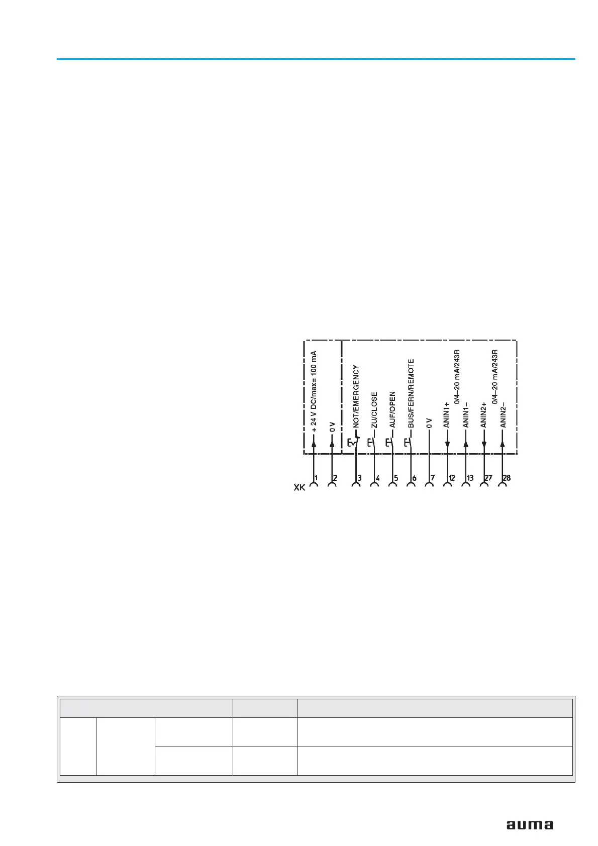
Figure J-2: Pin assignment for OPEN–CLOSE–EMERGENCY
(wiring diagram extract)
Feedback signals on the display
DeviceNet Note
S3 NOT READY
IND.
EXTERNAL
CONTROL
Bit 13.7 = 1
(page 34)
Operation via additional control inputs (i.e. BUS/REMOTE
connected to 24 V DC or 115 V AC as an option)
EMERGENCY
MODE
Bit 13.5 = 1
(page 34)
Emergency mode is active (the EMERGENCY function is
active and 0 V are applied at the EMERGENCY input).

 Loading...


