Actuator controls AUMATIC AC 01.1 / ACExC 01.1
DeviceNet Operation instructions
18
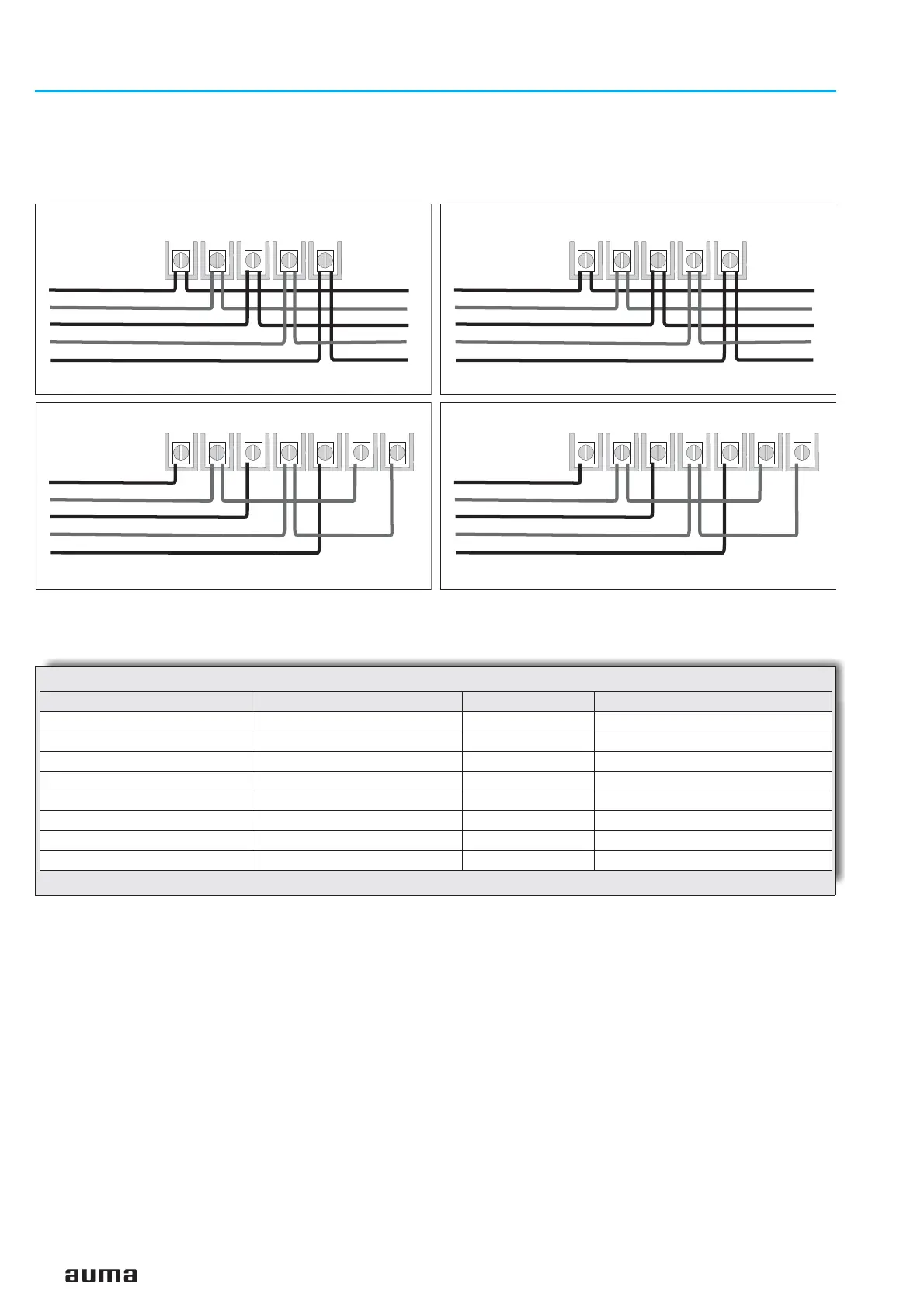
39 31 35 32 40
39 31 35 32 40 34 33
Figure D-13: Bus connection for channel 1
(standard)
Another bus station follows the actuator
Actuator is the final station in the DeviceNet trunk line
Black
Blue
Bare
White
Red
Black
Blue
Bare
White
Red
from previous
DeviceNet device
from previous
DeviceNet device
to next
DeviceNet device
49 47 36 48 50
49 47 36 48 50 38 37
Figure D-14: Bus connection for channel 2
(component redundancy only)
Another bus station follows the actuator
Actuator is the final station in the DeviceNet trunk line
Black
Blue
Bare
White
Red
from previous
DeviceNet device
to next
DeviceNet device
from previous
DeviceNet device
Black
Blue
Bare
White
Red
Technical data Motor power connections
1)
Protective earth Control pins
No. of contacts max. 3 1 (leading contact) 38 pins/sockets
Marking U1, V1, W1 according to VDE 1 to 24, 31 to 50
Voltage max. 550 V – 250 V
Current max. 25 A – 10 A
Type of customer connection Screws Screws Screws
Cross section max. 6 mm
2
6 mm
2
1.5 mm
2
Material: Pin / socket carrier Araldite / Polyamide Araldite / Polyamide Araldite / Polyamide
Contacts Brass (Ms) Brass (Ms) Brass (Ms) tin-plated
1) Suitable for copper wires. For aluminium wires it is necessary to contact AUMA.
Table 6: Technical data Ex-plug/ socket connector with terminal board for explosion-proof actuators

 Loading...


