EN13
C - INSTALLATION
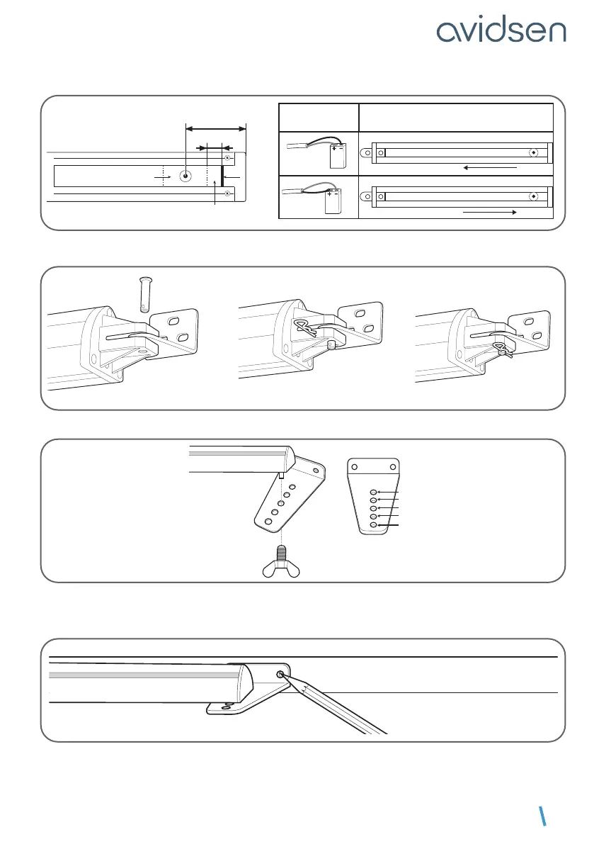
Please note: It is very important to follow this step otherwise the gate may not fully open or close properly!
P
I
L
E
9
V
P
I
L
E
9
V
Rod movement direction
Battery con
-
nection
blue
blue
brown
brown
carriage stop
free space
48mm
5mm
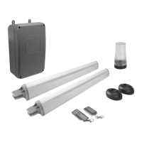
Assemble the actuator rotation axis with the post mounting bracket
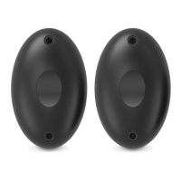
Usingabutteryscrew,assemblethegatemountingbracketwiththeactuator.Usetheholecorresponding
to distance D (see table p.12).
1
2
3
4
5
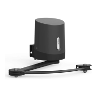
Close the gate by pressing it securely against its central stop, then rotate the actuator in order to install
the base of the gate mounting bracket onto the gate. Then mark the location of the two mounting holes
on the gate.