4-8
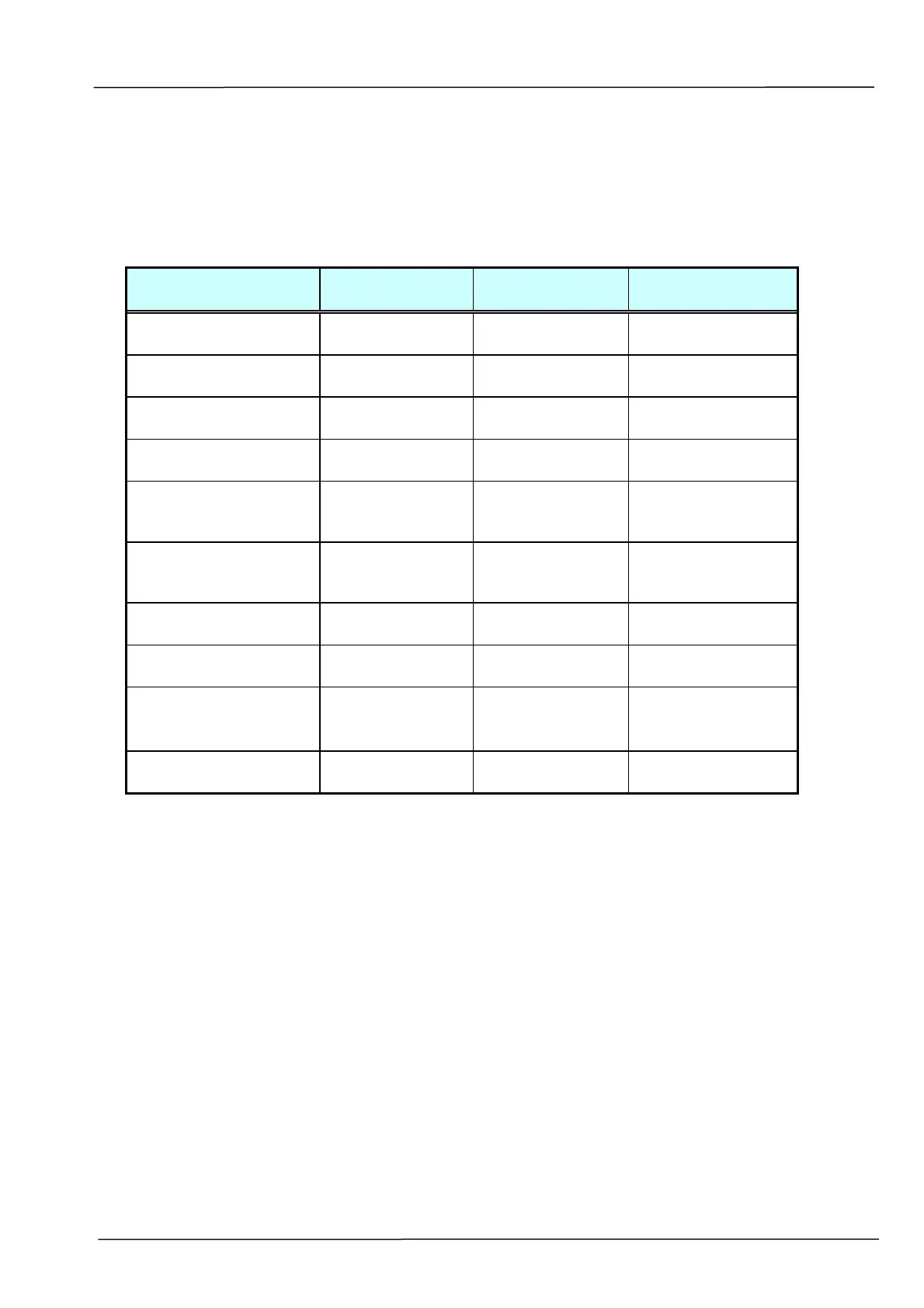
4.2.2 Tables
The tables in this section provide detailed troubleshooting information.
4.2.2.1 The Power LED does not go on
Cause Relevant Unit Check Method
Maintenance
Method
Unplugged from outlet None Visual check Insert the AC plug
into the outlet.
AC power unplugged
at unit
None Visual check Insert the AC cable
into unit.
Power switch is OFF None Visual check Turn the power
switch on.
AC voltage failure None AC outlet voltage
check
None
Power unit AC input
connector
disconnected
None Visual check Connect the
connector.
Power switch
connector
disconnected
None Visual check Connect the
connector.
Power unit-main PCBA
connection failure
None Visual check Connect the
connector.
Power unit output
voltage failure
Power unit Output voltage
(+24V) check
Replace the power
unit
PCBA Failure -main control
PCBA
-LED board
Tester check
(+24V, GND)
Remove the cause
or replace the
PCBA.
LED board-main PCBA
connection failure
None Visual check Connect the
connector
Table 4.3
*: Check method explains how to check the failed item.
The visual check can be made by physically observing the part or observing the
offline test display on the front panel. The tester check is made by checking the
voltage levels of the relevant units.