4-10
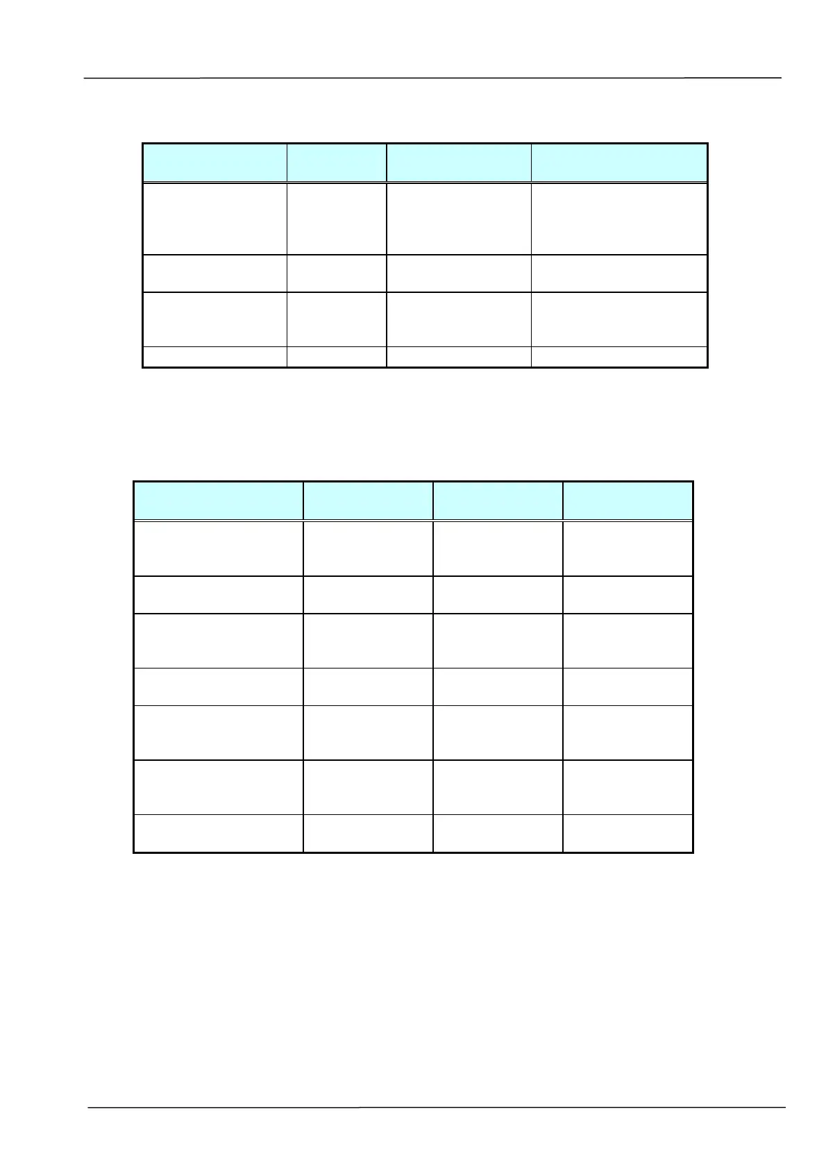
4.2.2.4 Large jitter
Cause Relevant
Unit
Check Method Maintenance
Method
Power supply-
main control
board connection
failure
None Visual check Connect the
connector.
Power supply fails Power
supply
Tester check
(+24V, GND)
Replace the power
supply.
Motor-main
control PCBA
connection failure
None Visual check Connect the
connector.
Motor failure Motor Visual check Replace the motor.
Table 4.6
4.2.2.5 Reading position deviation
Cause Relevant Unit Check Method Maintenance
Method
Power supply-main
control board
connection failure
None Visual check Connect the
connector.
Power supply fails Power supply Tester check
(+24V, GND)
Replace the
power supply.
Motor- main control
PCBA connection
failure
None Visual check Connect the
connector.
Motor failure Motor Visual check Replace the
motor
IR sensor board- main
control PCBA cable
failure
None Visual check Connect the
connector
IR sensor board- main
control PCBA cable
failure
Sensor board-
main control
PCBA cable
Tester or visual
check
Replace the IR
sensor cable
IR sensor board
failure
Sensor board Tester check Replace the
PCBA.
Table 4.7