5-72
Chapter 5. DETAILED DESCRIPTION OF EACH FUNCTION
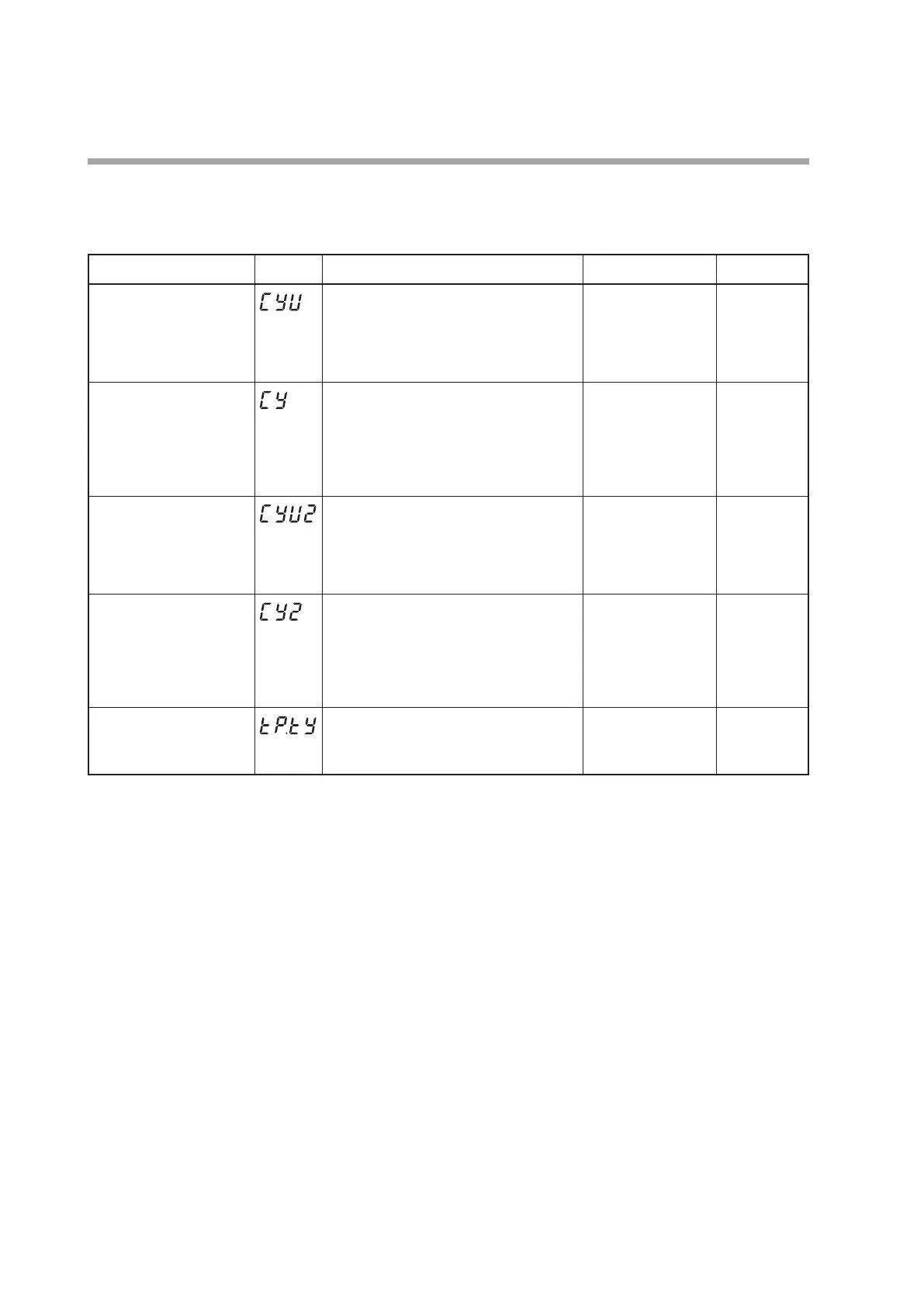
MV1/MV2 process
The time proportional cycle and time proportional cycle mode of MV1/MV2 can
be set.
Item (Bank) Display Contents Initial value User level
Time proportional cycle
unit 1
(Parameter bank)
0: 1s unit
1: Cycle fixed at 0.5s.
2: Cycle fixed at 0.25s.
3: Cycle fixed at 0.1s
If the set value is other than “0”, the time
proportional cycle 1 (
Cy
) cannot be set.
0 High function
Time proportional cycle 1
(Parameter bank)
5 to 120s (Output destination of MV1
includes the relay output.)
1 to 120s (Output destination of MV1 does
not include the relay output.)
If the time proportional unit 1 (
CyU
) ≠
0, this setting becomes invalid and the
setting becomes impossible.
10 or 2s Basic,
Standard,
High function
Time proportional cycle
unit 2
(Parameter bank)
0: 1s unit
1: Cycle fixed at 0.5s.
2: Cycle fixed at 0.25s.
3: Cycle fixed at 0.1s
If the set value is other than “0”, the time
proportional cycle 2 (
Cy2
) cannot be set.
0 High function
Time proportional cycle 2
(Parameter bank)
5 to 120s (Output destination of MV2
includes the relay output.)
1 to 120s (Output destination of MV2 does
not include the relay output.)
If the time proportional unit 2 (
CyU2
) ≠
0, this setting becomes invalid and the
setting becomes impossible.
10 or 2s Basic,
Standard,
High function
Time proportional cycle
mode
(Parameter bank)
0: Controllability aiming type
1: Operation service life aiming type (ON/
OFF operation is performed only once
within the time proportional cycle.
0 or 1 High function
• MV1 is the general term for the ON/OFF control output, time proportional
output, and time proportional output for heat side of the Heat/Cool control.
MV2 is the time proportional output for cool side of the Heat/Cool control.
• When MV1 is connected only to the voltage pulse output in the DO Assignment,
the display and setting of the time proportional cycle unit 1 (
CyU
) can be
performed.
• When MV1 is connected to any of the relay control output, voltage pulse
control output, and event output in the DO Assignment, the display and setting
of the time proportional cycle 1 (
Cy
) can be made. However, when the time
proportional cycle unit 1 (
CyU
) is other than “0”, the display and setting of the
time proportional cycle 1 (
Cy
) cannot be performed.
• When the Heat/Cool control is used and MV2 is connected only to the voltage
pulse output in the DO Assignment, the display and setting of the time
proportional cycle unit 2 (
CyU2
) can be performed.
• When the Heat/Cool control is used and MV2 is connected to any of the
relay control output, voltage pulse control output, and event output in the DO
Assignment, the display and setting of the time proportional cycle 2 (
Cy2
) can
be made. However, when the time proportional cycle unit 2 (
CyU2
) is other
than “0”, the display and setting of the time proportional cycle 2 (
Cy2
) cannot be
performed.
 Loading...


