6-14
Chapter 6. LIST OF DISPLAYS AND SETTING DATA
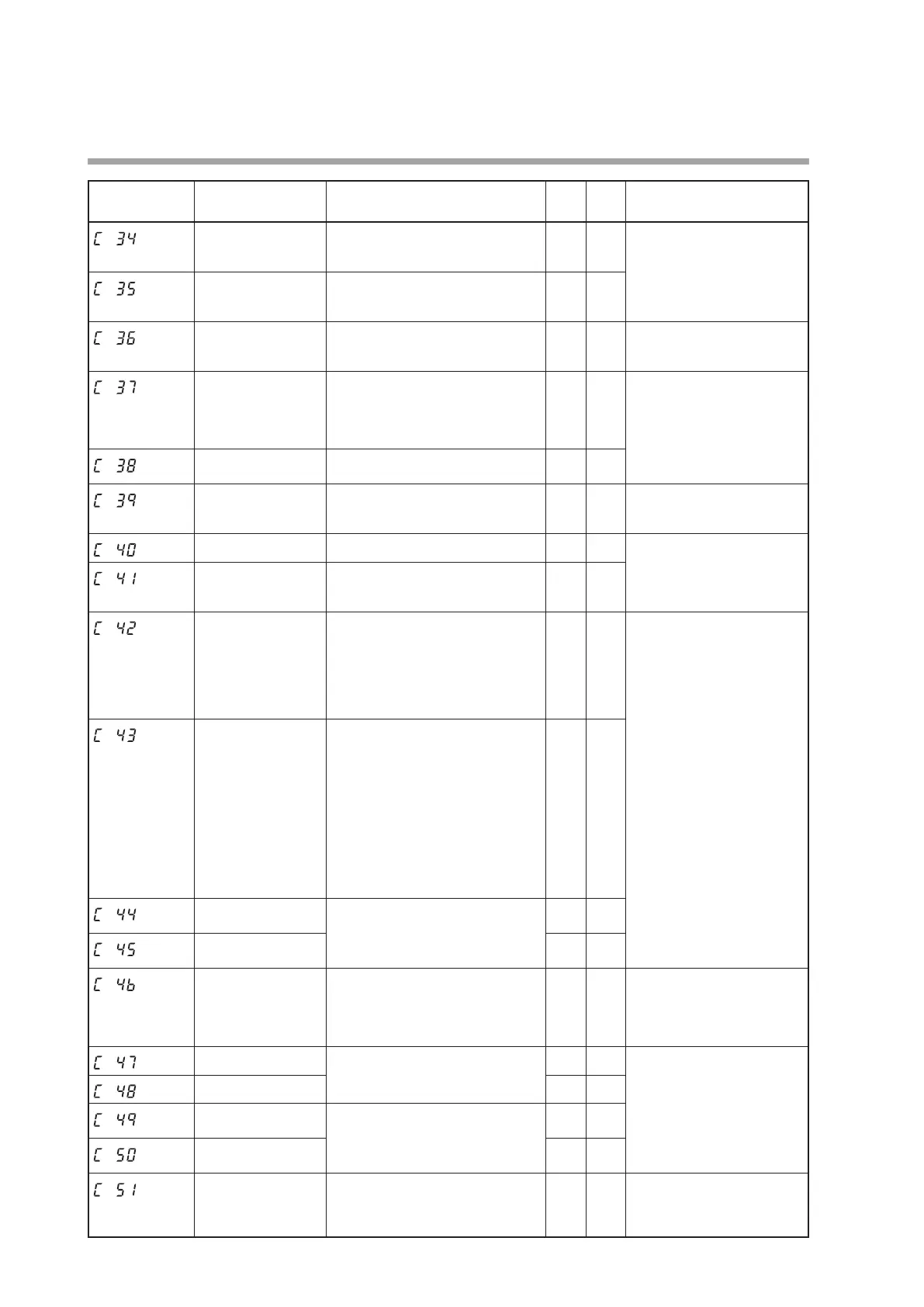
Display Item Contents
Initial
value
User
level
Notes
STEP PV start 0: None
1: Up start
2: Down start
0 2
Displayed when the SP ramp
type is the step operation
(
C3
1
≥2).
STEP loop 0: Stop (No loop)
1: Loop
2: Final step continued. (No loop)
0 2
CT1 operation type 0: Heater burnout detection
1: Current value measurement
0 0
Displayed when the optional
model has two current
transformer input points.
CT1 output 0: Control output 1
1: Control output 2
2: Event output 1
3: Event output 2
4: Event output 3
0 0
Displayed when the optional
model has two current transformer
input points and the CT1
operation type is set to "heater
burnout detection" (
C36
= 0).
CT1 measurement
wait time
30 to 300 ms
30 0
CT2 operation type Same as CT1 operation type
0 0
Displayed when the optional
model has two current
transformer input points.
CT2 output Same as CT1 output
0 0
Displayed when the optional
model has two current transformer
input points and the CT2
operation type is set to "heater
burnout detection" (
C39
= 0).
CT2 measurement
wait time
Same as CT1 measurement wait
time
30 0
Control output 1
range
Current output
1: 4 to 20 mA
2: 0 to 20 mA
Continuous voltage output
1: 1 to 5 V
2: 0 to 5 V
3: 0 to 10 V
1 0
Displayed when control
output 1 of the model is the
current output or continuous
voltage output.
The decimal point position
of the scaling low limit/high
limit becomes 1 digit after
the decimal point when
the control output 1 type
is related to the MV and CT.
When the control output 1
type is related to the PV and
SP, the decimal point position
becomes the same as that of
the PV.
The unit of scaling low limit/
high limit depends on the
output type of control output 1.
When the output type relative
to MV and MFB; %.
When the ouput type relative
to PV and SP; same as PV.
When the output type relative
CT; ampere (current value).
Control output 1
type
0: MV
1: Heat MV (for heat/cool control)
2: Cool MV (for heat/cool control)
3: PV
4: PV before ratio, bias, and filter
5: SP
6: Deviation
7: CT1 current value
8: CT2 current value
9: MFB (including estimated MFB)
10: SP+MV
11: PV+MV
0 0
Control output 1
scaling low limit
-1999 to +9999
The decimal point position and unit
may vary depending on control
output 1 type.
0 0
Control output 1
scaling high limit
100.0 0
Control output 1 MV
scalable bandwidth
0 to 9999
The decimal point position and unit
are same as for PV.
200 0 If the controller model uses
current output for control
output 1 and if the control
output 1 type is SP+MV or
PV+MV, this setting is displayed.
Control output 2 range
Same as control output 1.
1 0
Displayed when control
output 2 of the model is the
current output or continuous
voltage output.
The decimal point position
and unit is same as that of
control output 1.
Control output 2 type
3 0
Control output 2
scaling low limit
-1999 to +9999
The decimal point position and unit
may vary depending on control
output 2 type.
0 0
Control output 2
scaling high limit
1000 0
Control output 2 MV
scalable bandwidth
0 to 9999
The decimal point position and unit
are same as for PV.
200 0
If the controller model uses current
output for control output 2 and if
the control output 2 type is SP+MV
or PV+MV, this setting is displayed.
(Continue on next page.)

 Loading...


