6-13
Chapter 6. LIST OF DISPLAYS AND SETTING DATA
(Continue on next page.)
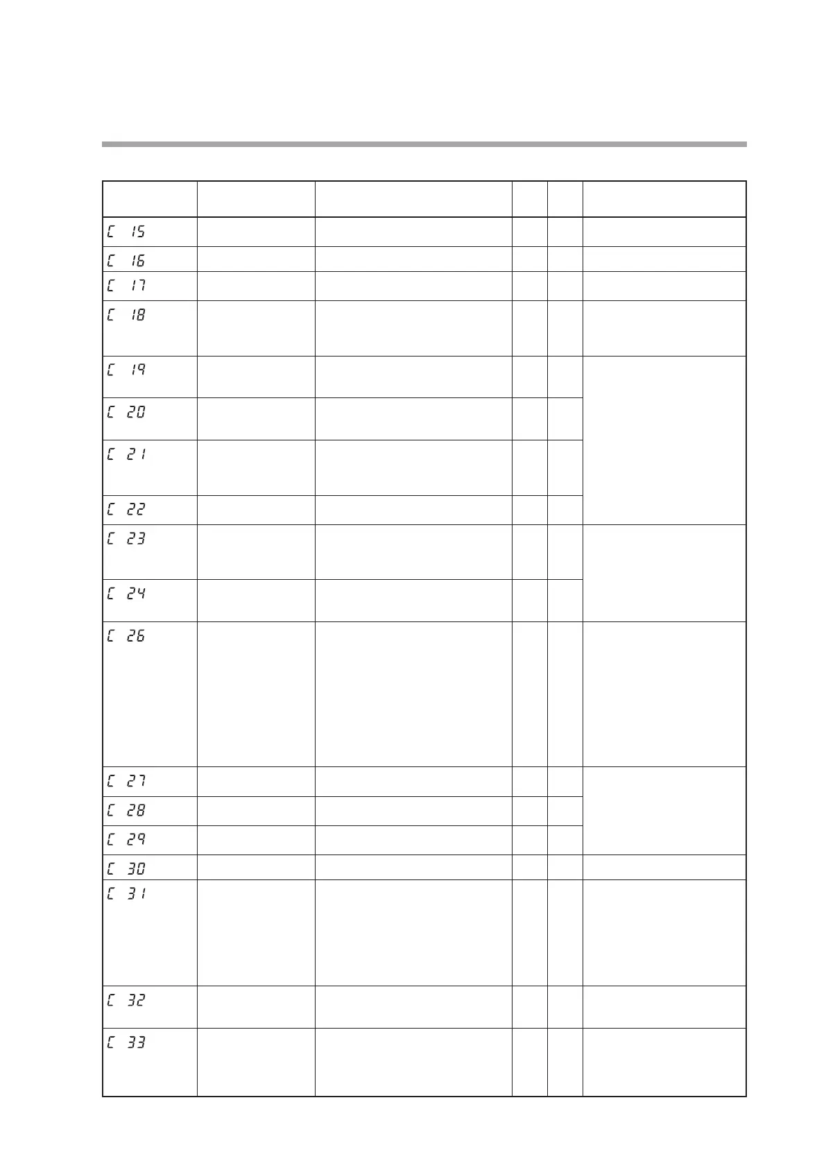
Display Item Contents
Initial
value
User
level
Notes
Output operation at
PV alarm
0: Control calculation is continued.
1: Output at PV alarm is output.
0 2
Output at PV alarm -10.0 to +110.0 %
0.0 2
Output at READY
(Heat)
-10.0 to +110.0 %
0.0 1
Output at READY
(Cool)
-10.0 to +110.0 %
0.0 1
Displayed when the control
method is other than the ON/OFF
control (
CtrL
≠0) and the heat/
cool control (
C26
= 1) is used.
Output operation
at changing Auto/
Manual
0: Bumpless transfer
1: Preset
0 1
Displayed when the control
method is other than the ON/
OFF control (
CtrL
≠0).
When the operation mode is
the MANUAL mode at power
ON, the preset MANUAL
value (
C20
) becomes the
Manipulated Variable (MV).
Preset MANUAL
value
-10.0 to +110.0 %
(Used when the operation mode is
the MANUAL mode at power ON.)
0.0 or
50.0
1
Initial output type
(mode) of PID
control
0: Auto
1: Not initialized
2: Initialized (If SP value different
from the current value is input.)
0 2
Initial output of PID
control
-10.0 to +110.0 %
0.0 or
50.0
2
PID Decimal point
position
0: No decimal point
1: 1 digit after decimal point
(Decimal point of integral time and
derivative time)
0 2
Displayed when the control
method is other than the ON/
OFF control (
CtrL
≠0).
Zone PID operation 0: Disabled
1: Changed by SP
2: Changed by PV
0 2
Heat/Cool control 0: Not used
1: Used
0 0
Displayed when the control output
type is other than R1 (motor
drive relay output), and when the
control method is other than the
ON/OFF control (
CtrL
≠0).
When set at “1”, the control action
is set to the reverse action (
C
14
= 0), the preset MANUAL value
(
C20
) is set to “50.0”, and the
initial output of the PID control
(
C22
) is changed to “50.0”.
Heat/Cool 0: Normal
1: Energy saving
0 1
Displayed when the Heat/
Cool control is used (
C26
= 1).
Heat/Cool control
dead zone
-100.0 to +100.0 %
0.0 0
Heat/Cool control
change point
-10.0 to +110.0 %
50.0 2
LSP system group 1 to 8
1 0
SP ramp type 0: Standard
1: Multi-ramp
2: Step operation
When the power is turned ON again,
the step operation is stopped (READY).
3: Step operation
When the power is turned ON
again, the step operation is reset.
0 2
SP ramp unit 0: 0.1 U/s
1: 0.1 U/min
2: 0.1 U/h
1 2
"0.1 U" shows that the decimal
point position of the PV is
shifted one digit rightward.
STEP time unit 0: 0.1 s
1: 1 s (“min. s” is displayed on the
console.)
2: 1 min (“h. min” is displayed on the
console.)
0 2
Displayed when the SP ramp
type is the step operation
(
C3
1
≥2).
(Continue on next page.)
 Loading...


