4-6
Chapter 4. WIRING
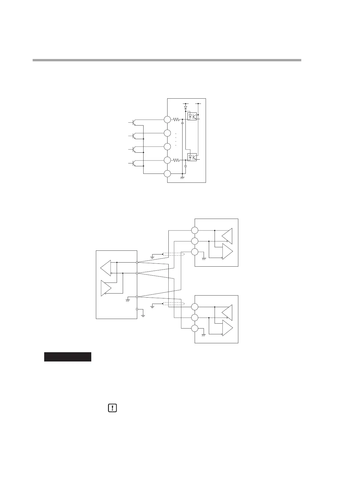
Connection of open collector output to digital input
The following shows a connection example when connecting to four digital input
points.
This unit
18
19
20
21
24
5 V
Connection of communication (RS-485) cable
3-wire system
22
23
24
22
Master station
DA
DA
DB
DB
SG
SG
SG
FG
+
–
This unit (slave station)
This unit (slave station)
Shield
Shield
23
24
IMPORTANT
Terminating resistor
• Do not connect any terminating resistor in the communication path.
Doing so might cause the communication failure.
• Even though any units requiring the terminating resistor in the
communication path, do not connect any terminating resistor.
Handling Precautions
• Do not connect DA and DB. Doing so might cause damage to this unit.
• Ground the shield line to one point on one end of the cable.
• Be sure to connect SG terminals each other.
Failure to do so might cause unstable communications.
 Loading...


