5-8
Chapter 5. DETAILED DESCRIPTION OF EACH FUNCTION
Zener barrier adjustment
When the PV input is RTD and uses the Zener barrier, the Zener barrier needs to
be adjusted. Additionally, if three wiring resistances to the PV input terminal have
any variation even though the Zener barrier is not used, the Zener barrier must also
be adjusted.
When using an input other than RTD, this adjustment is not needed and cannot be
performed.
Item (Bank) Display Contents Initial value User level
Special function
(Setup bank)
0 to 15
5: Zener barrier adjustment enabled.
0
(This value becomes
zero (0) when the
power is turned ON.)
High function
Zener barrier adjustment
(Setup bank)
–20.000 to +20.00
(However, “–20.00” is displayed as “–19.99”.)
The value can be changed with the
adjustment.
The numeric value cannot be directly input
with the manual operation.
0.00 High function
Adjusting procedures
Follow the steps below to adjust the Zener barrier.
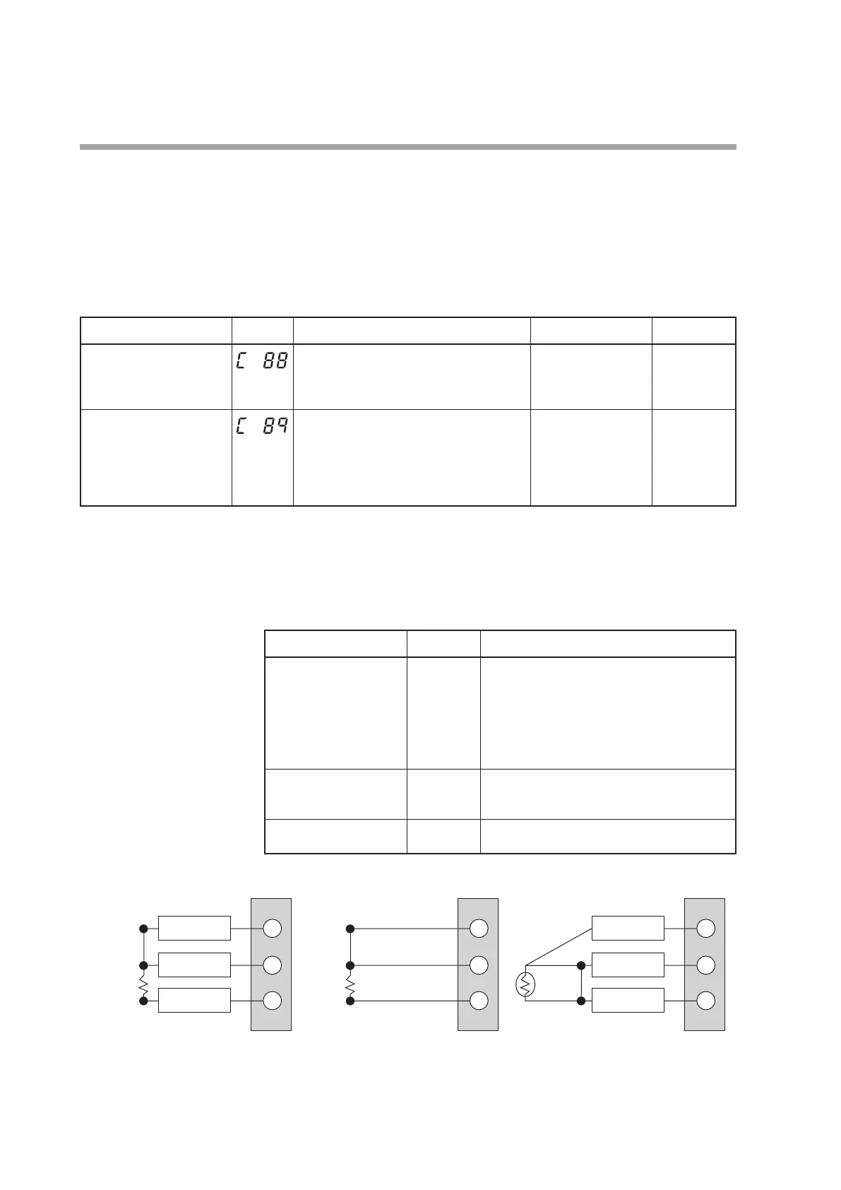
(1) Turn off the power to the unit and apply wiring No. 1. To adjust the long wires
without a zener barrier, apply wiring No. 2.
Applicable PV range type
Wiring status
Wiring contents
41 to 52, 63 to 68 1
Remove the RTD, connect a 100.00 resistor
between zener barriers A and B, and connect B to C.
For connections, use resistors that meet the
following specifications.
Allowable tolerance: ±0.05 %. Rated power: 0.1
W minimum. Recommended resistor: C2610E
(100 ) made by PCN Corporation
41 to 68 2 Remove the RTD from between the extension
wires, connect a 100.00 resistor between
zener barriers A and B, and connect B to C.
41, 42, 45, 46, 65 to 68 3 Connect zener barriers A and B at the RTD
terminals.
Wiring No 1
100.00 Ω
This unit
C
B
A
Zener barrier
Zener barrier
Zener barrier
10
11
12
Long wiring
Long wiring
Long wiring
Shorted
100.00 Ω
C
B
A
10
11
12
Shorted
C
B
A
Zener barrier
Zener barrier
Zener barrier
10
11
12
(2) Turn ON the power to the unit and set “5” to [
C88
: Special function].
(3) Display [
C89
: Zener barrier adjustment].
 Loading...


