1-1
Chapter 1 Functionality, Configuration, and Structure of this Device and CommStaff
Chapter 1 Functionality, Configuration, and Structure of
this Device and CommStaff
This chapter describes the basic functionality, structure, and configuration of this device, as well
as the basic functionality and configuration of CommStaff, the communicator required to operate
this device. Please read this chapter to gain an understanding of the basics of this device and
CommStaff if using the device for the first time.
1-1 Functionality and Configuration of this Device
1-1-1 Functionality and Configuration of this Device
This device measures differential pressure using a differential pressure sensor on a compound
semiconductor sensor, and transmits gauge pressure, absolute pressure, flow rate, and liquid level
data. In order to accurately measure differential pressure, compensation based on changes in
static pressure and temperature is necessary. By measuring these changes using the differential
pressure sensor and a temperature sensor on the compound semiconductor sensor, and performing
comparison operations relative to actual measurement data stored at the time of factory shipping,
the measured differential pressure is adjusted to the true differential pressure and output. This
device is composed of a differential pressure sensor, a temperature sensor, a static pressure sensor,
a multiplexer, and an A/D converter in the meter body, along with amicroprocessor, various data
storage elements, and a D/A converter in the transmission unit.
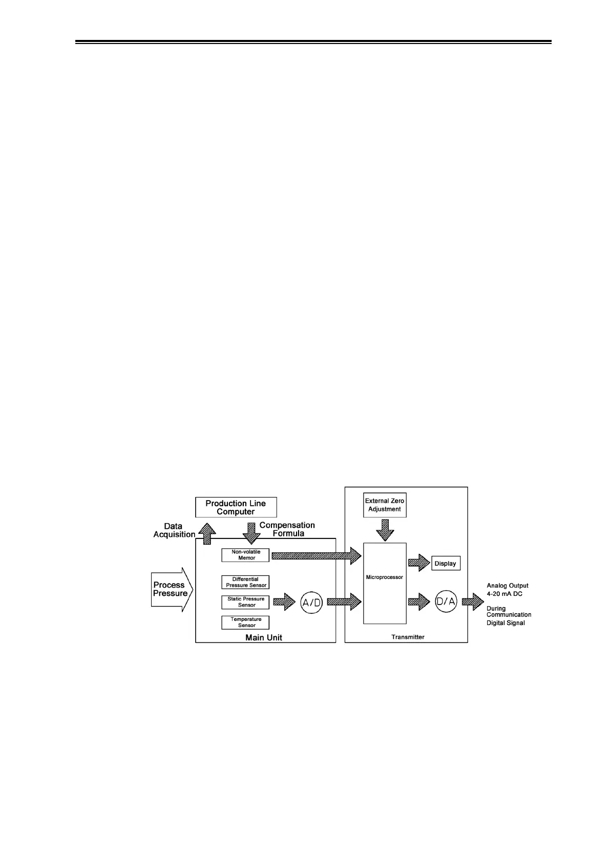
The diagram below illustrates the basic functionality and configuration of this device.
The flow rate, pressure, and liquid level of the process fluid are conveyed to the differential
pressure sensor on the compound semiconductor chip in the main unit.
The output of this sensor undergoes A/D conversion simultaneously with the temperature and
static pressure detected by the temperature sensor and static pressure sensor on the compound
semiconductor sensor.
These converted signals are processed by the microprocessor, converted again to a 4-20 mA DC
analog signal corresponding to the specified range, and output.
Figure 1-1. Block Diagram of this Device
Non-volatile memory:
(EEPROM)
The input-output characteristics, temperature characteristics, static
pressure characteristics, device type, settable range, etc., of the meter body
are stored here. In addition, a variety of setting data for the transmission
unit is held here even when the power is turned off.
A/D: Analog signal from the compound semiconductor sensor is converted to
adigital signal.
D/A: Digital signal for the compensated differential pressure is converted to
ananalog signal.