A-14
Appendix A Maintenance and Troubleshooting of this Device
A3-3 Parameter configuration procedures
To diagnose clogging in the connecting pipe using the pressure frequency index, parameters must
be set. Use the configuration procedure below.
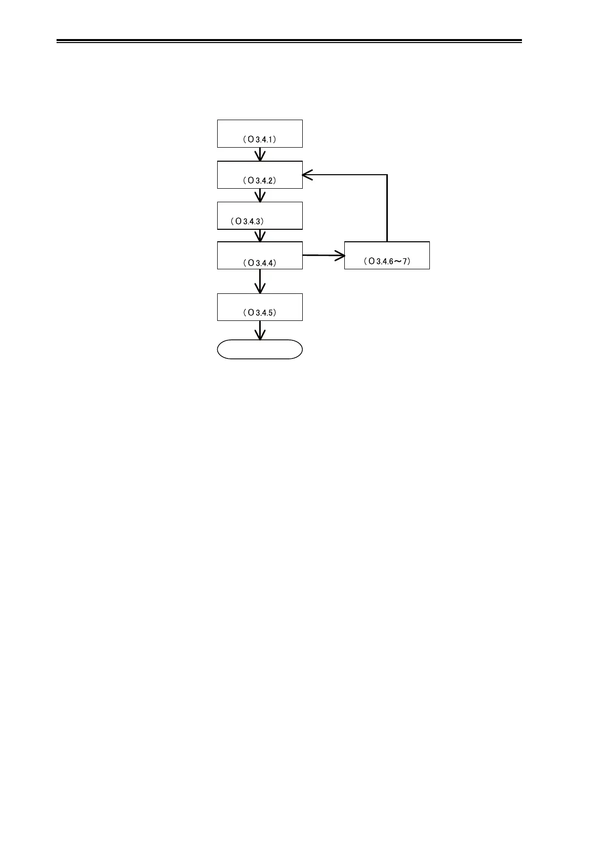
Preparation
Acquisition of index values
under normal conditions
Clogging simulation test
Judge the possibility
of diagnosis
Parameter adjustment
If not possible
Possible
Note:
Setting of the alarm
Start the diagnosis
Preparation (see section A3-4-1): Initialize the parameters in preparation for obtaining the index
values.
Acquisition of index values under normal conditions (see section A3-4-2): Obtain index values
under normal conditions, and also the maximum and minimum index values.
Clogging simulation test (see section A3-4-3): Operate the valve of the connecting pipe to simulate
a clog and obtain index values. Do a both-side clogging simulation test that simulates clogging
on both the high and low pressure sides, and a one-side clogging simulation test that simulates
clogging on one side only.
Note:
If you cannot conduct the clogging simulation test, skip sections A3-4-3 to A3-4-7, and go to
section A3-4-8.
Judging the possibility of diagnosis (see section A3-4-4): Determine whether or not you can
differentiate between a normal state and a simulated clogged state by comparing their index values.
Setting the alarm (see section A3-4-5): If diagnosis is judged to be possible, adjust the parameters
shown below to set an alarm based on the collected index values. When the configuration process
is complete, the diagnosis can begin.
Press Freq Index Alarm Use
Press Freq Index Low Limit
Press Freq Index High Limit
Parameter adjustment (see section A3-4-6 and 7): If distinguishing the two states is not possible,
analyze the cause, adjust the parameters shown below, and then return to “Acquisition of index
values under normal conditions.”
Press Freq Index Sensor Selection
Press Freq Filter Constant
Press Freq Calc PV High Limit
Press Freq Calc PV Low Limit