3-29
Chapter 3 Starting and Stopping this Device
3-4 Measurement Using the JTC Model
3-4-1 Liquid Level Measurement
(1) Preparing for Operation
(i) Checking the minimum liquid level (zero position) and zero point input
during input equalization
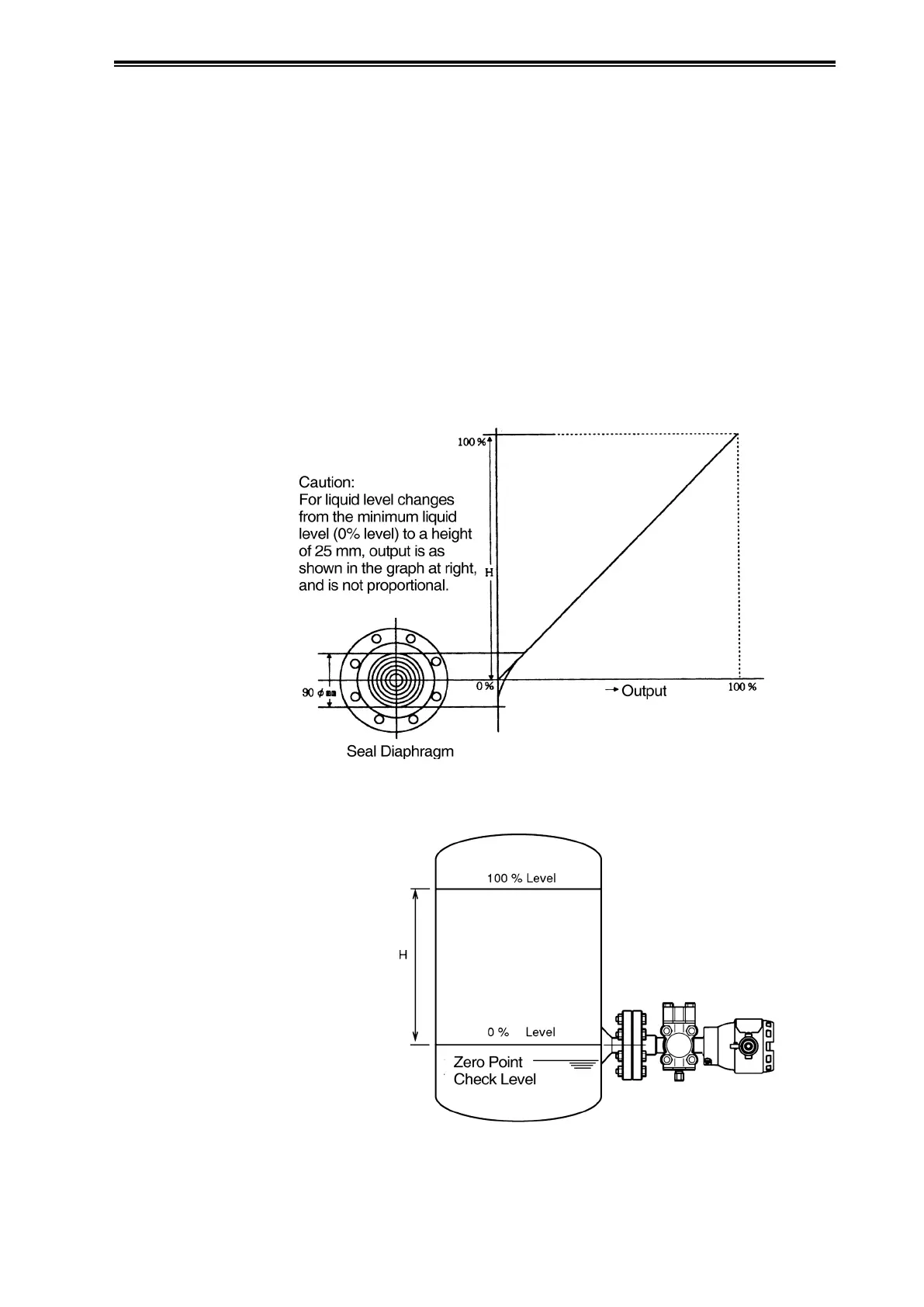
The zero position liquid level is taken to be the center of the seal diaphragm on the surface of the
process connection flange of the device (see Figures 3-4 and 3-5). As a result, the measurement
range H extends from the center of the transmitter flange to the height of the usage range. However,
when performing the zero point check, lower the liquid level to below the bottom of the seal
diaphragm. In addition, for a sealed tank wet leg, remove the sealing liquid. That is, check the
zero point after putting the diaphragms on the high pressure side and the low pressure side into
an equalized pressure state. For information regarding the method of checking, see the operation
manual for the communicator.
Figure 3-4. Minimum Liquid Level Characteristics
Figure 3-5. Zero Position Determination