2-31
Chapter 2 Installation of this Device
2-3-2 Pressure Measurement Piping (JTD/JTG/JTA Model)
Warning
When doing the piping work, ensure that the connections between the connecting pipe
parts and the transmitter and three-way manifold valve are able to maintain a reliable
seal. If sealing is inadequate, there is a danger that the measured fluid will leak out and
cause scalding and other harmful health effects. If the measured fluid is harmful to the
human body, take safety measures such as wearing goggles or a mask so that it does not
adhere to the skin or the eyes, become inhaled, etc.
(1) Piping
(i) Introduction
For the JTD model, connect the high pressure side to the process pipe, and open the low pressure
side to the atmosphere. In this case, in order to prevent rainwater from entering, use a vertical
downward-facing opening to the atmosphere. For the JTG and JTA models, connect the low
pressure side to the process pipe.
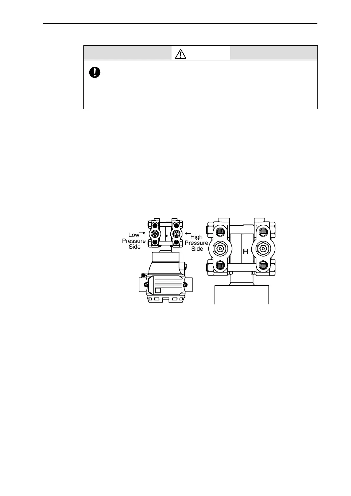
(ii) High pressure side mark on this device
An “H” is displayed on the high pressure side of the main unit of this device to indicate high
pressure, so be sure to check this during piping in order to avoid mistakes. The side without a mark
is the low pressure side.
Figure 2-37. Mark on High Pressure Side of Main Unit
(iii) Selection of pipes
For connecting pipes from the process, select pipe schedule numbers and nominal thicknesses in
accordance with process side selection criteria (conditions such as process pressure). Diameter 1/2B,
schedule number 80 steel pipes are one example of connecting pipes which are commonly used.
(iv) Required parts example
When doing the piping work, refer to the piping example diagrams, and have the following parts
ready. Select the rating, material, etc., of each part based on process side selection standards.
• Pipes
• A master valve, and a manual master valve if necessary
• Unions or Flanges
• T-Joints
• Drain Valve
• Gas Vent Plugs