3-2
Chapter 3 Starting and Stopping this Device
3-1 Operation Preparations
3-1-1 Communicator Connection
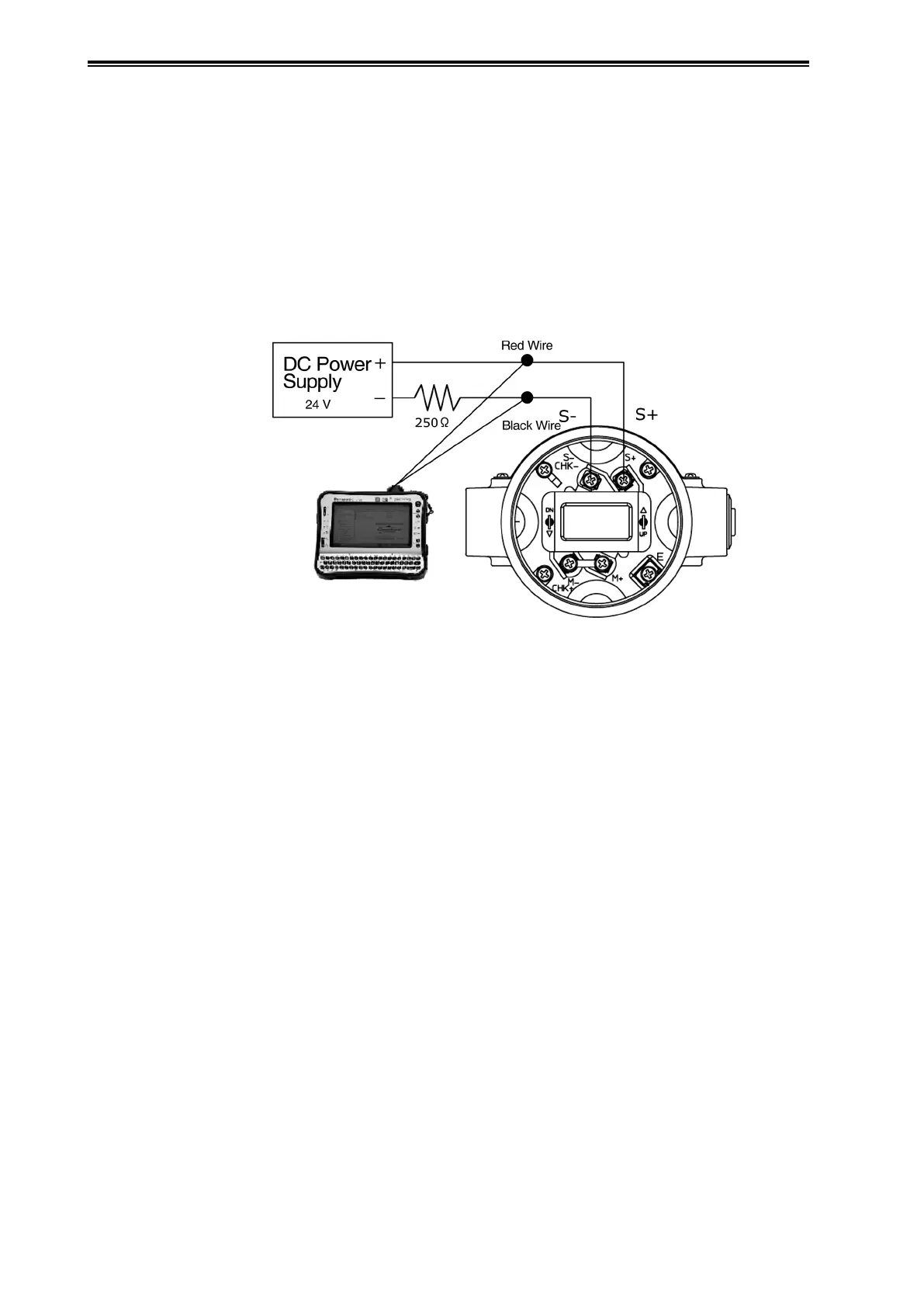
The figure below shows the wiring when connecting a communicator to this device.
For SFN/DE communication using CommStaff, be sure to connect the communication cables to
the terminals of this device as shown below.
Red wire: Supply + (S+) terminal
Black wire: Supply - (S-) terminal
* For communication with the communicator, external load resistance of at least 250 Ω
is required. If the receiver side load resistance is less than 250 Ω, insert a loop with
the necessary resistance.
Figure 3-1. Communicator Connection