1-4
Chapter 1 Functionality, Configuration, and Structure of this Device and CommStaff
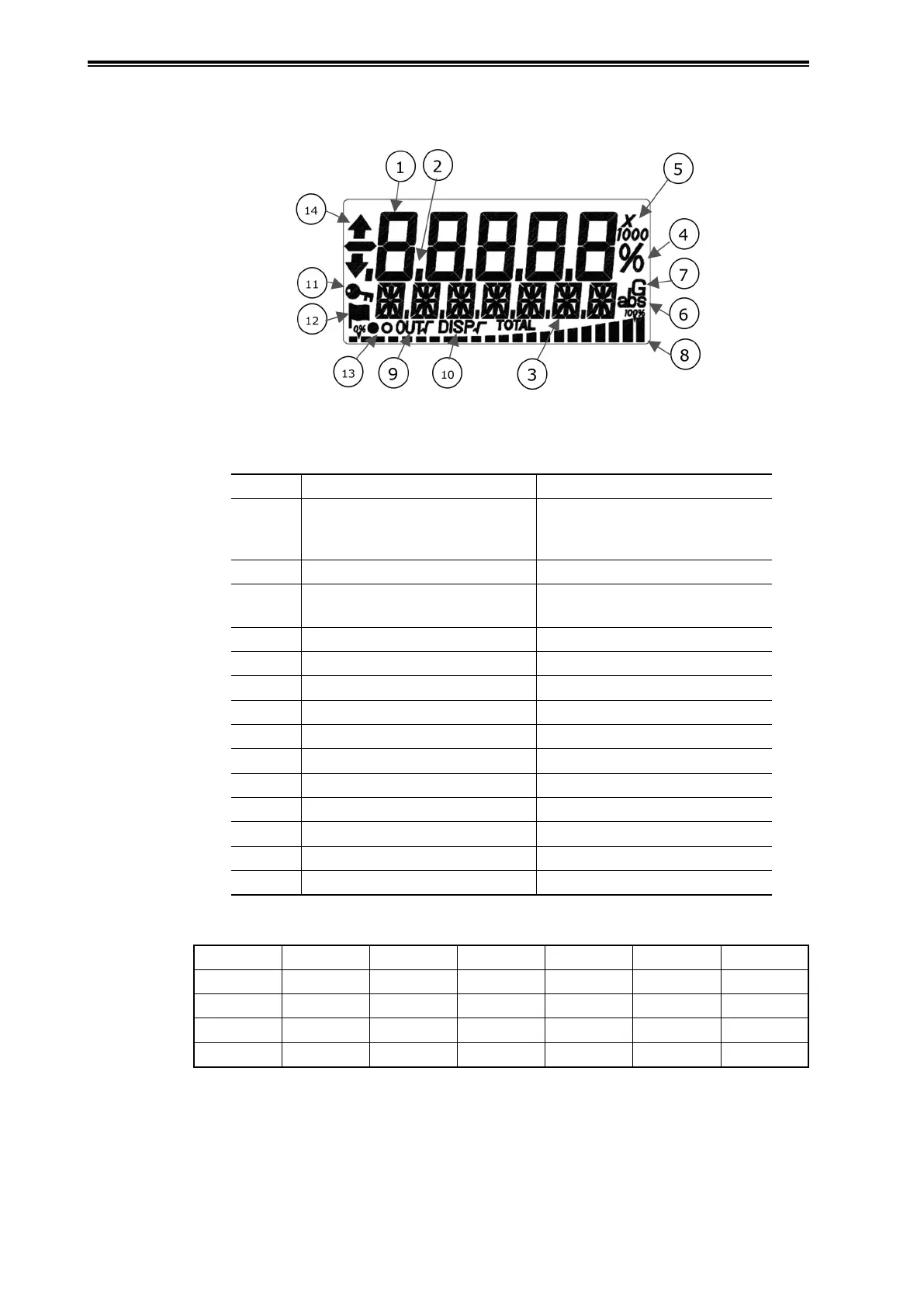
1-1-3 Indicators (Optional)
The names of the display indicators are as follows.
Figure 1-5. Indicator Display Unit
Table 1-1. Indicator Display Unit
No. Indicator/Symbol Indicator Description
1 Main indicator (4.5 digits)
Value, error
Process variable (engineering
unit scale, real pressure), %
Status number
2 Decimal point (4 digits) Decimal point
3 16-segments indicators (7 digits) Units*, status
External zero adjustment
4 % Percentage
5 Exponent ×10, ×100, ×1000
6 Absolute Pressure abs
7 Gauge Pressure G
8 Bar graph Bar graph of output %
9 Output square root OUT √
10 Display square root DISP √
11 Key symbol Write-protected state
12 Flag symbol Diagnostic History
13 Display update symbol Alternating display:
and
14 External zero adjustment
or
*
Selectable units list (SI units)
kPa MPa Pa hPa kPaG MPaG kPa abs
MPa abs Pa abs hPa abs g/cm
3
kg/m
3
m
3
l
kl ml/h l/h kl/h t/h m
3
/h km
3
/h
l/min kl/min m
3
/min kl/d m
3
/d t/d kg/h
mm m % t kg none