1-2
Chapter 1 Functionality, Configuration, and Structure of this Device and CommStaff
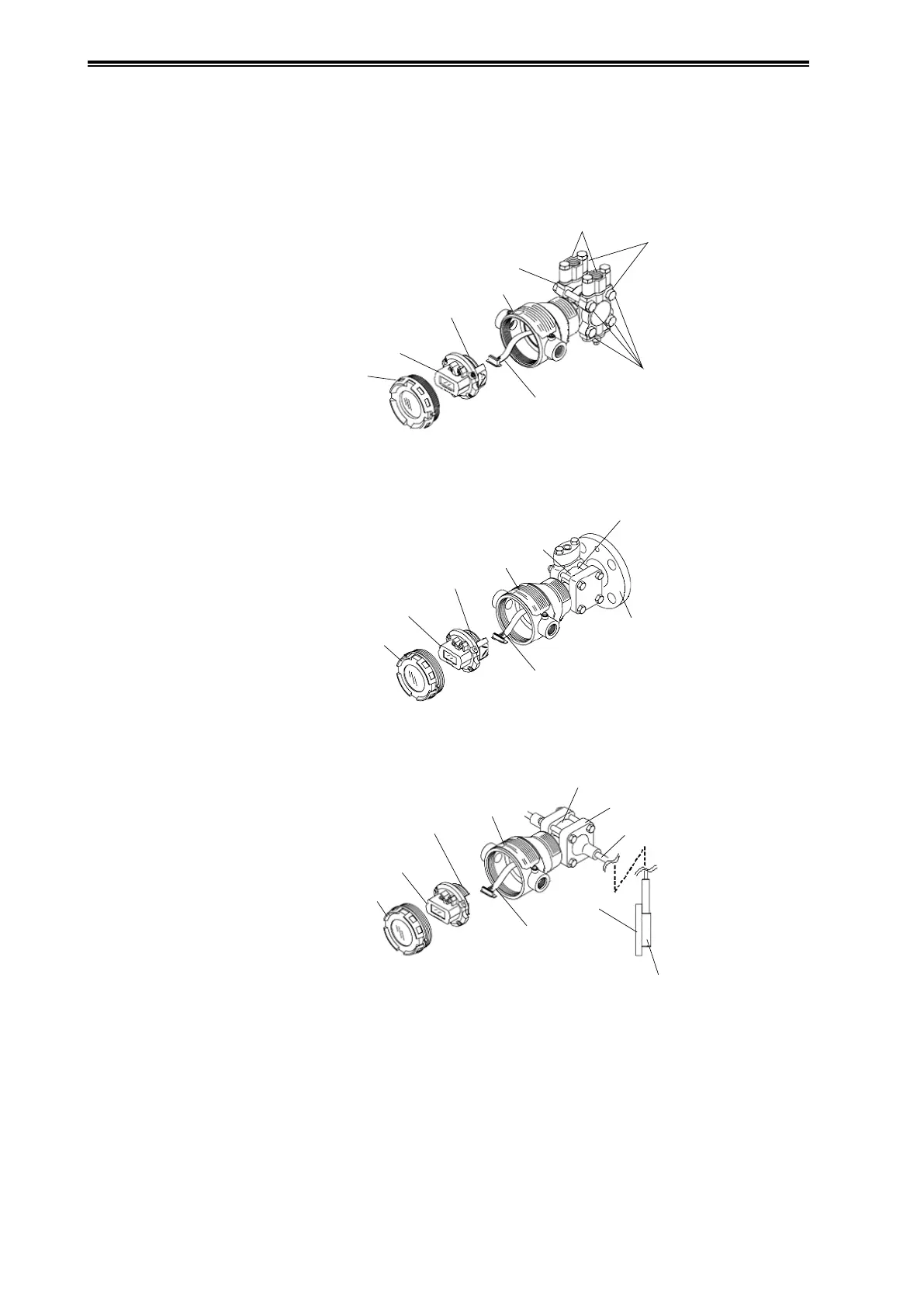
1-1-2 Part Names
This device is composed primarily of a main unit, an electronics module, a terminal block with
integrated indicators, a transmission unit case, and a case cover.
The following diagram shows the structure and part names of this device.
Adapter Flanges
Cover Flanges
Main Unit
Transmitter Case
Electronics Module
Terminal Block with
Integrated Indicators
Case Cover
Flexible Cable
Bolts and Nuts
Figure 1-2. Structure of JTD Model
Flange /
Bolts and Nuts
Detector Section
Transmitter Case
Electronics Module
Terminal Block with
Integrated Indicators
Case Cover
Flexible Cable
Figure 1-3. Structure of JTC Model
Capillary Tube
Flange
Detector Section
Transmitter Case
Electronics Module
Terminal Block with
Integrated Indicators
Case Cover
Flexible Cable
Figure 1-4. Structure of JTE and JTH Models